Custom Solderable Snap Domes for Automotive Controls
Consistent tactile response, reliable electrical contact and 1,000,000+ press cycles, engineered around your automotive control design, PCB or FPC layout, assembly process and cost target.
Automotive Control Snap Domes — Key Performance Requirements
Automotive control buttons must deliver the same clear response throughout years of repeated use, temperature change, vibration and exposure to dust or oil. Our custom solderable snap domes are designed for stable tactile feedback and dependable conductivity in switches and control modules. Their geometry, dimensions, force profile, travel, plating and delivery format can be tailored to the application.
Clear Tactile Feedback
A distinct click gives the driver or passenger immediate confirmation. Actuation force is controlled for a uniform feel across buttons and production lots.
Low Resistance Contact
Contact resistance can be specified below 1 ohm. Gold-plated contact areas resist oxidation and sulfuration and support stable signal transmission.
Long Service Life
Designs can be rated for 1,000,000 or more press cycles across an operating range of -40°C to +85°C, with controlled loss of force over the service life.
Fast Return
The dome returns immediately after release, reducing the risk of slow rebound, sticking or failure to reset.
Dust & Contamination Resistance
Contact geometry and optional sealing treatments help limit the effect of dust, oil and other contaminants on electrical performance.
How to Choose Materials and Plating for Automotive Snap Domes?
Material and surface treatment are selected around contact performance, fatigue life, solderability, temperature exposure and cost.
| Option | Recommended Use | Technical Notes |
|---|---|---|
| Gold plating | Low-resistance contacts and signal circuits | Typical thickness: 0.025-0.2 μm. Thicker plating can be specified for higher-reliability applications. |
| Tin plating | Applications where solderability and cost are priorities | Good solderability and lower cost than gold. Tin-whisker risk and higher contact resistance must be considered. |
| Nickel underplate | Barrier layer beneath gold or tin | Typical thickness: 1.25-3 μm. Improves adhesion and helps limit copper diffusion. |
| Custom combinations | Application-specific electrical and assembly requirements | Silver plating, nickel plus gold, nickel plus tin and selective plating are available. |
Why Choose Shanyo Automotive Snap Domes?
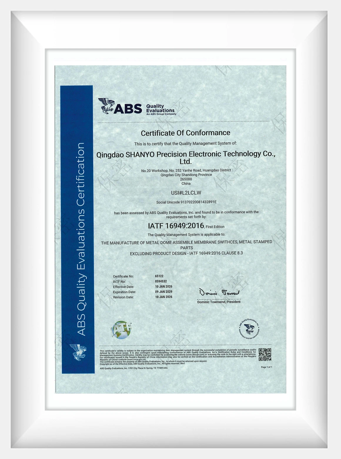
IATF 16949 Certified
Our automotive quality management system is certified to IATF 16949, supporting consistent quality, process control, and traceability for automotive applications.
Custom Formed Geometry
Non-standard shapes and dimensions can be developed to support asymmetric mounting, multiple contact points, and other space-constrained structures.
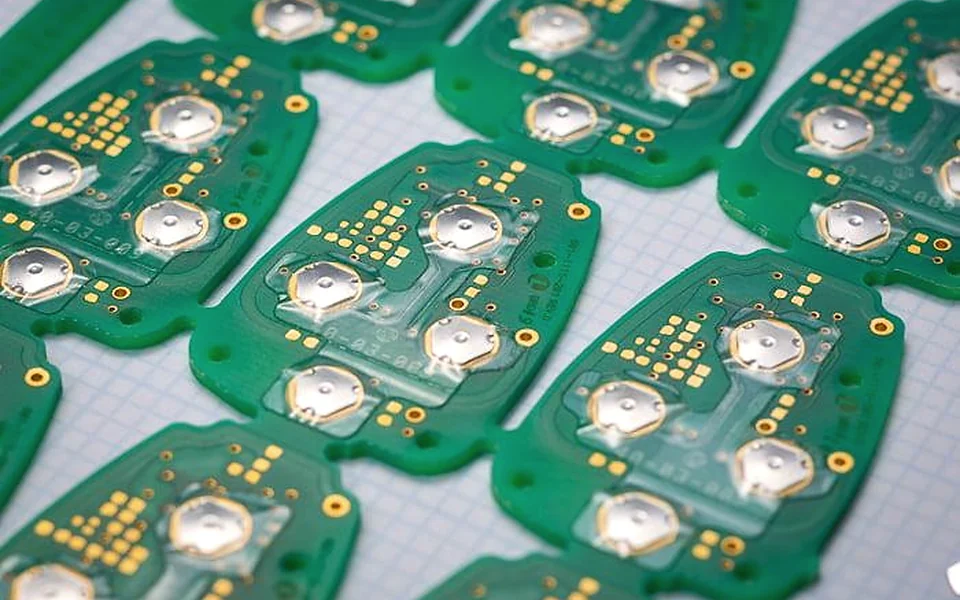
Direct Soldering
The component can be soldered directly to a PCB or FPC by SMT or manual soldering, without a separate fixing bracket.
Efficient Placement
Tape-and-reel delivery supports high-speed automated SMT placement and stable feeding in volume production.
Design for Reliable Return
Edge finishing, installation clearance, and mating geometry are optimized to prevent interference during thermal expansion and vibration.
- 1 Configuration
- 2 Contact details
Automotive Snap Domes
Step 2 of 2
Request a quote
Your configuration will be included in the email sent to the site administrator.
Request sent
Thank you. Your quote request has been sent to our team.
Technical Resources for Automotive Snap Domes
Common Automotive Snap Dome Issues and Solutions
| Challenge | Failure Mode | Likely Cause | Shanyo Solution |
|---|---|---|---|
| Poor contact | Intermittent signal or excessive resistance | Oxidation, sulfuration, contamination or insufficient plating | Specify a corrosion-resistant plating system; control thickness and cleanliness; use a self-wiping contact geometry. |
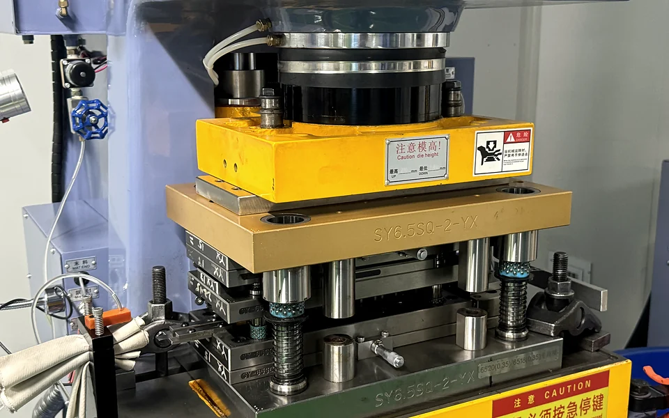
| Early fatigue | Loss of force or fracture before 1,000,000 cycles | Insufficient fatigue strength, uncontrolled heat treatment or residual stamping stress | Select a suitable copper alloy such as C17200; control hardness and heat treatment; include stress relief where required. |
| Inconsistent feel | Large force variation or an indistinct click | Material hardness variation, tool wear or thickness variation | Inspect incoming material; maintain tooling; control stamping capability; measure force and travel in process. |
| PCB or FPC damage | Scratches, wear or circuit damage | Edge burrs or assembly misalignment | Deburr and round edges; improve locating features and assembly fixtures. |
| Failure to return | Slow rebound or a stuck button | Insufficient clearance, housing deformation or trapped debris | Allow for -40°C to +85°C thermal movement; improve sealing and dimensional control. |
| SMT defects | Insufficient solder, tombstoning or placement shift | Poor solderability, uneven plating or oxidation during storage | Validate solderability; control plating uniformity; define humidity-controlled or nitrogen storage and shelf life. |
| Tin whiskers | Potential short circuit during service | Inadequate tin-plating process or no barrier layer | Use a nickel barrier layer; apply post-plating stress relief; consider matte tin or another suppression system. |
| High-temperature relaxation | Reduced force and contact pressure | Material relaxation or plating diffusion at elevated temperature | Select a material with suitable stress-relaxation performance and keep service temperature within the validated limit. |