
Understanding Custom Membrane Switch Layer Structure
Membrane switches appear deceptively simple from the outside. A flat panel with printed graphics, some buttons, maybe a few indicator windows. But underneath that surface lies a carefully engineered stack of functional layers working together.
Each layer within a custom membrane switch serves specific purposes. Some provide structure. Others create electrical functionality. Still others deliver the tactile experience users expect. Understanding how these layers interact helps appreciate the engineering behind seemingly basic interfaces.
The number of layers varies by design complexity. Simple switches might contain just three or four layers. More sophisticated assemblies stack eight or more layers to achieve required functionality. Every layer adds thickness, cost, and capability.
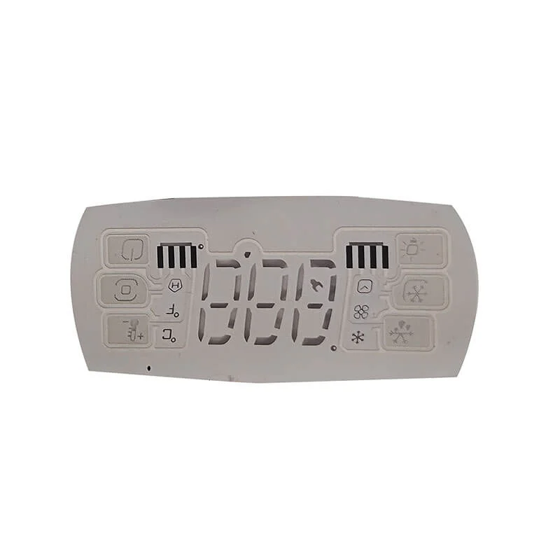
The Graphic Overlay in Custom Membrane Switch Assemblies
Primary Functions
The graphic overlay sits atop everything else, forming the user-facing surface. This layer handles multiple responsibilities simultaneously.
Key functions include:
- Displaying graphics, text, and symbols
- Protecting underlying layers from environment
- Providing desired surface texture and appearance
- Transmitting user input to layers beneath
- Housing display windows and LED light pipes
Material selection affects all these functions. Polyester films dominate most applications due to balanced properties and reasonable cost. Polycarbonate offers alternatives when specific characteristics matter more.
Graphic Printing Considerations
Printing occurs on the overlay’s underside, protecting inks from wear and chemical exposure. This subsurface printing extends graphic life considerably compared to surface printing approaches.
Printing methods commonly used:
- Screen printing for solid colors and text
- Digital printing for photographic images
- Combination approaches for complex designs
Ink selection matters too. Standard formulations work for indoor applications. UV-resistant inks prevent fading in outdoor or window-adjacent installations. A well-specified custom membrane switch matches ink properties to expected environmental exposure.
Adhesive Layers Throughout Custom Membrane Switch Construction
Bonding Functions
| Adhesive Location | Primary Purpose | Typical Type |
|---|---|---|
| Overlay to circuit | Component bonding | Pressure sensitive |
| Circuit to spacer | Layer assembly | Pressure sensitive |
| Rear mounting | Equipment attachment | Pressure sensitive or thermal |
| Selective areas | Tactile dome retention | Transfer adhesive |
Performance Specifications
Adhesive selection involves balancing multiple factors that sometimes conflict with each other.
Considerations include:
- Temperature range for application and service
- Chemical resistance requirements
- Bond strength needs
- Thickness constraints
- Cost targets
Aggressive adhesives bond reliably but make repositioning impossible during assembly. Lower-tack options allow adjustment but may release under stress. Matching adhesive properties to actual needs requires understanding application conditions thoroughly.
A custom membrane switch designer considers these factors when specifying adhesives throughout the construction.
Circuit Layers in Custom Membrane Switch Design
Conductive Trace Construction
The circuit layer transforms a membrane switch from decorative panel into functional interface. Conductive inks printed on flexible substrates create the electrical pathways connecting switches to external electronics.
Silver-based conductive inks predominate due to excellent conductivity and reasonable cost. Carbon inks offer alternatives where silver migration concerns exist or cost pressures demand cheaper solutions. Copper flex circuits provide highest performance when applications justify added expense.
Circuit substrates typically use polyester film for standard applications. Polyimide substrates handle higher temperatures and enable more demanding constructions.
Single Versus Dual Layer Circuits
Simple custom membrane switch designs use single circuit layers with interleaved traces. Pressing buttons brings opposing contacts together, completing circuits.
More complex designs employ dual circuit layers:
- Upper circuit carries one set of contacts
- Lower circuit carries mating contacts
- Spacer separates layers until actuation
Dual layer constructions enable more sophisticated circuits and accommodate higher switch densities. The added complexity increases cost and thickness accordingly.
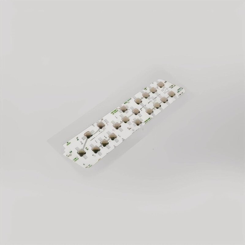
Tactile Feedback Components Within Custom Membrane Switch Layers
Metal Dome Integration
Metal domes provide crisp tactile feedback many users prefer. These formed metal components nest within the layer stack, typically sitting atop lower circuit contacts.
Dome integration approaches include:
- Individual dome placement in adhesive pockets
- Dome arrays on carrier tape
- Domes bonded directly to overlay underside
Dome specifications vary considerably:
| Parameter | Range | Effect |
|---|---|---|
| Diameter | 4mm to 20mm+ | Actuation area size |
| Force | 100g to 500g+ | Press effort required |
| Travel | 0.1mm to 0.3mm | Movement sensation |
| Snap ratio | 30% to 70% | Feedback intensity |
Alternative Tactile Solutions
Not every custom membrane switch uses metal domes. Polyester domes offer softer feedback at lower cost. Embossed overlays provide visual and tactile button definition without internal components.
Non-tactile designs suit certain applications perfectly well. Where feedback matters less or cost constraints dominate, flat membrane switches without tactile elements work adequately. If you want to know more about custom membrane switch, please read Custom Membrane Switch: Tailoring Every Layer to Your Needs.
FAQ
How many layers does a typical custom membrane switch contain?
Layer count varies by design complexity. Basic switches contain four to five layers. Tactile versions with metal domes typically have five to seven layers. Complex assemblies with shielding, backlighting, or multiple circuit layers may exceed eight layers. Each additional layer adds capability along with thickness and cost.
Can individual layers be replaced if damaged?
Generally no. Custom membrane switch layers bond permanently during manufacturing. Field replacement of individual layers proves impractical. Complete assembly replacement represents the standard service approach when damage occurs.
Which layer fails most commonly during service life?
The graphic overlay experiences most direct wear from user contact and environmental exposure. Graphic degradation from cleaning chemicals or physical abrasion represents common failure mode. Proper material and treatment selection for expected conditions minimizes overlay failures significantly.