Getting dome sheets to work properly with flexible printed circuits sounds straightforward until actually attempting it. The combination seems natural enough — both are thin, both flex, both serve modern compact electronics. But achieving reliable integration involves details that aren’t immediately obvious. Misalignment by fractions of a millimeter creates mushy tactile feedback. Wrong adhesive choices cause delamination months later. Thermal mismatch buckles assemblies.
Ultra-thin ドームシート integration into FPC requires attention to materials, tolerances, assembly processes, and environmental factors. When done correctly, the result is a reliable tactile interface that survives millions of actuations. When done poorly, warranty claims follow.
Understanding Dome Sheet Basics for FPC Integration
Before discussing integration techniques, understanding what makes these components work matters.
What Dome Sheets Actually Are
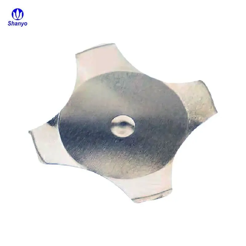
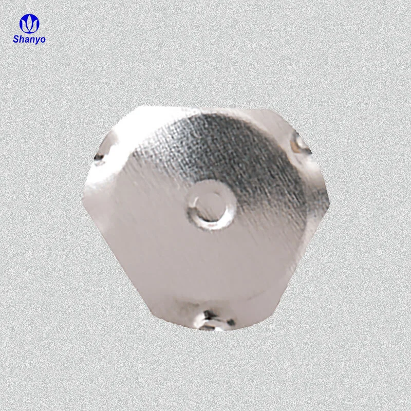
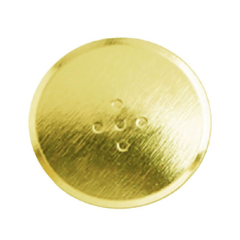
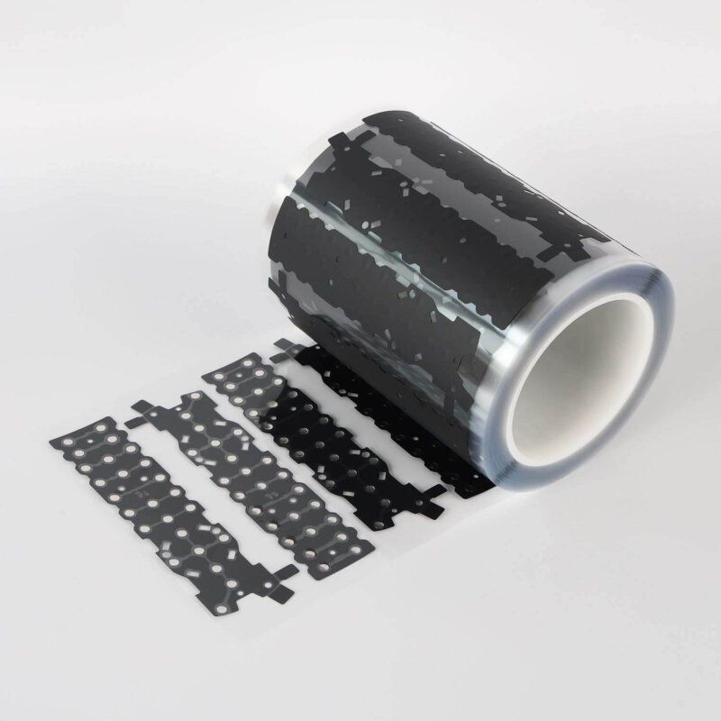
A dome sheet consists of small metal domes — typically stainless steel — held in precise positions by an adhesive carrier layer. When pressed, each dome collapses with a distinct snap, making electrical contact with the underlying circuit. Release the pressure and the dome springs back to its original shape.
The “ultra-thin” designation typically means total thickness under 0.3mm, sometimes as thin as 0.15mm. These dimensions create challenges. There’s essentially no margin for error. Everything must align precisely.
Why FPC Pairing Makes Sense
Flexible printed circuits offer advantages that rigid PCBs cannot:
- Conformability to curved surfaces
- Reduced assembly thickness
- Weight savings in portable devices
- Dynamic flexing capability for certain applications
- Three-dimensional routing possibilities
Combining an ultra-thin dome sheet with FPC creates extremely compact switch assemblies suitable for wearables, medical devices, remote controls, and slim consumer electronics. The pairing works — but demands careful execution.
Critical Factors for Dome Sheet Integration Success
Several variables determine whether an integration succeeds or creates problems.
Material Compatibility
| コンポーネント | Key Consideration | Potential Issue |
|---|---|---|
| ドーム素材 | Stainless steel grade affects tactile feel and life | Corrosion in harsh environments |
| Dome carrier | Adhesive type and release characteristics | Incomplete transfer or shifting |
| FPC substrate | Polyimide vs. PET affects flexibility and heat resistance | Thermal mismatch during reflow |
| Contact pads | 金、銀、カーボンインク | Oxidation affecting contact reliability |
| Bonding adhesive | Acrylic vs. silicone chemistry | Delamination, outgassing, or creep |
Mismatched materials create problems that emerge gradually. An adhesive that seems fine initially might fail after thermal cycling. Contact pads that work in the lab corrode in humid field environments. Testing under realistic conditions catches these issues before production.
Dimensional Tolerances
Ultra-thin assemblies leave no room for sloppiness. Dome position tolerance typically needs to stay within ±0.1mm to ensure proper alignment with FPC contact pads. The dome sheet carrier, FPC artwork, and assembly process all contribute to final alignment accuracy.
Critical dimensions include:
- Dome-to-dome spacing accuracy
- FPC pad-to-pad artwork tolerance
- Registration between dome sheet and FPC during lamination
- Pocket depth if using recessed mounting
Stack-up analysis reveals whether combined tolerances allow reliable contact. Individual components might each be within spec while the assembly still fails due to tolerance accumulation.

Dome Sheet Assembly Process Considerations
Surface Preparation
FPC surfaces must be clean and properly prepared before dome sheet application. Contamination — flux residue, fingerprints, dust — interferes with adhesive bonding and can affect electrical contact reliability.
Recommended preparation steps:
- Solvent cleaning to remove organic contamination
- Inspection for surface defects or debris
- Environmental control during assembly (temperature and humidity)
- Handling procedures to prevent recontamination
- Optional plasma treatment for difficult-to-bond surfaces
Skipping preparation steps invites failures that appear weeks or months post-assembly. The adhesive bond might seem adequate initially but degrades under thermal cycling or humidity exposure.
アライメント方法
Achieving precise dome sheet to FPC alignment requires appropriate tooling. Options range from simple to sophisticated:
- Manual alignment using visual registration marks
- Pin registration with tooling holes in both components
- Vision-assisted pick-and-place systems
- Dedicated lamination fixtures with mechanical registration
Volume production typically justifies fixturing investments. Prototype or low-volume work might rely on careful manual alignment — though this approach tests patience and introduces variability.
Lamination Parameters
Bonding pressure, temperature, and time affect adhesive performance. Too little pressure creates weak bonds. Too much pressure can deform domes or squeeze adhesive into unwanted areas. Temperature activation requirements vary by adhesive type.
A typical lamination profile might involve:
- Initial tack at room temperature with light pressure
- Full bonding at elevated temperature (if required by adhesive)
- Controlled cooling to prevent stress buildup
- Post-cure if specified by adhesive manufacturer
Process documentation matters. What works in the lab needs translation into repeatable production procedures.

Troubleshooting Common Dome Sheet Integration Problems
- Mushy or inconsistent tactile feedback — usually misalignment or contamination on contact surfaces
- Intermittent electrical contact — pad contamination, insufficient dome travel, or damaged domes
- Delamination over time — adhesive incompatibility, surface preparation failure, or environmental exposure
- Multiple domes actuating simultaneously — excessive bonding pressure deforming domes or insufficient spacing
- Domes not returning properly — mechanical interference, damaged domes, or adhesive migration
Systematic troubleshooting isolates root causes. Random adjustments without understanding the failure mechanism rarely solve problems permanently. If you want to know more about dome sheet, please read ドームシートとは.
よくあるご質問
What thickness qualifies as an ultra-thin dome sheet?
Industry definitions vary somewhat, but ultra-thin typically refers to dome sheet assemblies with total thickness below 0.3mm. Some designs achieve 0.15mm to 0.2mm total stack-up using smaller dome diameters and thinner carrier materials. These extremely thin versions demand even tighter tolerances and more careful handling during assembly. Standard dome sheets might run 0.4mm to 0.6mm thick for comparison.
Can dome sheets be reworked after bonding to FPC?
LRework is technically possible but rarely practical. Removing a bonded dome sheet risks damaging the FPC surface, leaving adhesive residue, or distorting the flexible circuit. If rework is anticipated, using lower-strength repositionable adhesives during prototyping makes sense — then switching to permanent bonding for production. Generally, treating dome sheet application as a one-way operation encourages getting it right the first time.
How many actuations should a properly integrated dome sheet assembly survive?
Quality dome sheets typically rate for 1 million to 5 million actuations depending on dome size, material, and actuation force. Proper integration shouldn’t significantly reduce this life expectancy. Failures occurring well before rated life usually indicate integration problems — misalignment causing edge contact, contamination, or adhesive issues — rather than inherent dome limitations. Environmental factors like humidity, temperature cycling, and contamination exposure also affect achievable life in real applications.