Обеспечить правильную работу купольных плёнок в сочетании с гибкими печатными платами кажется простым делом, пока не попробуешь это сделать на практике. Такое сочетание кажется вполне естественным — и те, и другие имеют тонкий профиль, гибкие и используются в современной компактной электронике. Однако для надёжной интеграции необходимо учитывать детали, которые не сразу бросаются в глаза. Смещение всего на доли миллиметра приводит к нечеткой тактильной обратной связи. Неправильный выбор клея приводит к отслоению через несколько месяцев. Несоответствие тепловых характеристик вызывает деформацию сборок.
Ультратонкий лист купола Интеграция в гибко-печатную плату (FPC) требует тщательного подхода к выбору материалов, допусков, процессов сборки и учета факторов окружающей среды. При правильном выполнении в результате получается надежный тактильный интерфейс, способный выдержать миллионы циклов срабатывания. В случае некачественного выполнения работы следуют претензии по гарантии.
Основы использования купольных пластин для интеграции гибко-печатных плат
Прежде чем перейти к рассмотрению методов интеграции, важно понять, что обеспечивает работу этих компонентов.
Что на самом деле представляют собой купольные листы
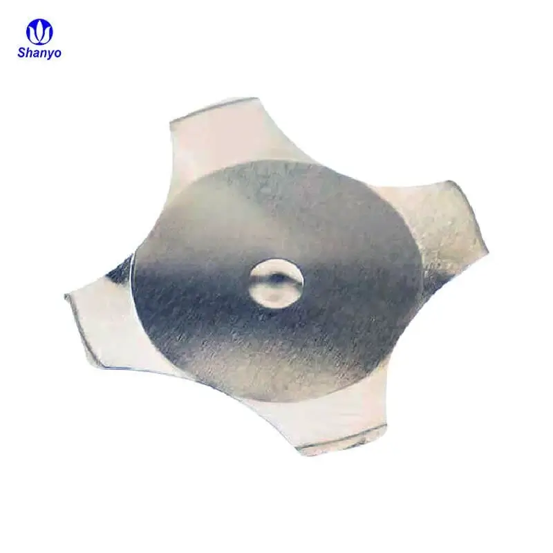
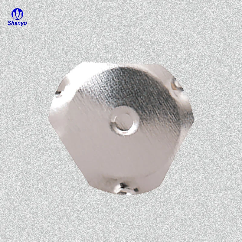
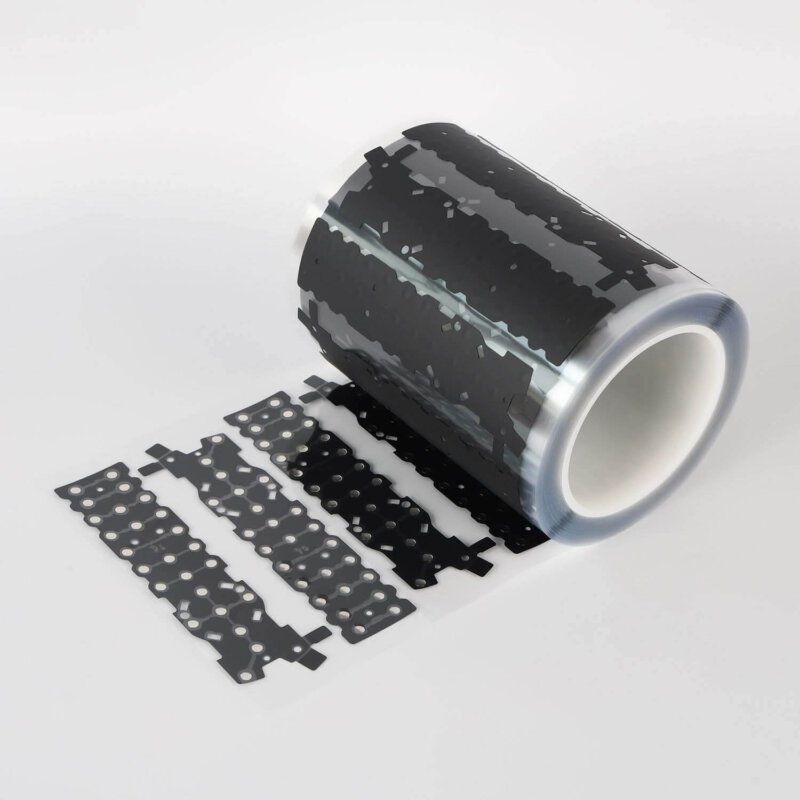
Купольная пленка состоит из небольших металлических куполов — как правило, из нержавеющей стали, — которые удерживаются в точно заданных положениях с помощью клеевого слоя-носителя. При нажатии каждый купол с характерным щелчком сжимается, устанавливая электрический контакт с расположенной под ним цепью. При снятии давления купол возвращается в исходное состояние.
Обозначение “ультратонкий” обычно означает, что общая толщина не превышает 0,3 мм, а иногда составляет всего 0,15 мм. Такие размеры создают определенные сложности. По сути, здесь нет места для ошибок. Все должно быть точно выровнено.
Почему объединение FPC имеет смысл
Гибкие печатные платы обладают преимуществами, недоступными для жестких печатных плат:
- Прилегание к изогнутым поверхностям
- Уменьшенная толщина сборки
- Снижение веса портативных устройств
- Возможность динамического изгиба для определенных областей применения
- Возможности трёхмерной трассировки
Сочетание ультратонкого куполообразного листа с гибкой печатной платой (FPC) позволяет создавать чрезвычайно компактные переключающие узлы, подходящие для носимых устройств, медицинского оборудования, пультов дистанционного управления и тонкой бытовой электроники. Такое сочетание работает — но требует тщательного подхода.
Ключевые факторы успешной интеграции купольных листов
Успех интеграции или возникновение проблем зависят от ряда факторов.
Совместимость материалов
| Компонент | Основные аспекты, которые следует учитывать | Возможная проблема |
|---|---|---|
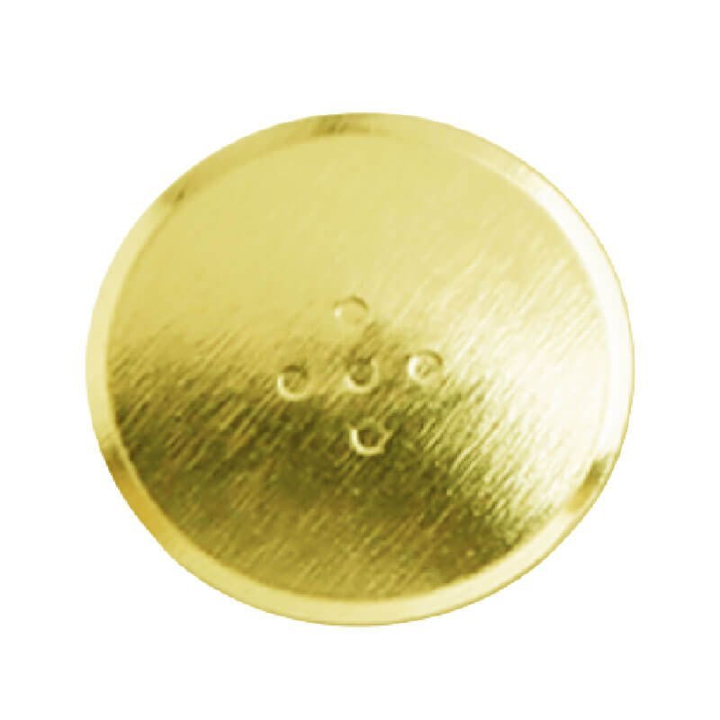
| Материал купола | Марка нержавеющей стали влияет на тактильные ощущения и срок службы | Коррозия в агрессивных средах |
| Держатель купола | Тип клея и характеристики отрыва | Неполная передача или смещение |
| Подложка FPC | Сравнение полиимида и ПЭТ влияет на гибкость и термостойкость | Термическое несоответствие во время пайки методом рефлоу |
| Контактные площадки | Золотые, серебряные или углеродные чернила | Окисление, влияющее на надежность контактов |
| Клей для склеивания | Химические свойства акрила и силикона | Расслоение, газовыделение или ползучесть |
Несовместимые материалы приводят к проблемам, которые проявляются постепенно. Клей, который поначалу кажется подходящим, может выйти из строя после циклов термического воздействия. Контактные площадки, которые нормально работают в лабораторных условиях, подвергаются коррозии во влажной эксплуатационной среде. Испытания в реальных условиях позволяют выявить эти проблемы ещё до начала серийного производства.
Допуски на размеры
Ультратонкие сборки не допускают никакой неаккуратности. Допуск по положению купола, как правило, должен находиться в пределах ±0,1 мм, чтобы обеспечить правильное совмещение с контактными площадками гибкой печатной платы (FPC). На конечную точность совмещения влияют как несущая пластина купола, так и макет гибкой печатной платы (FPC), а также процесс сборки.
К критическим параметрам относятся:
- Точность расстояния между куполами
- Допуски на макеты «контакт к контакту» для гибко-печатных плат
- Зазор между листом купола и гибкой печатной платой (FPC) во время ламинирования
- Глубина углубления при встраиваемом монтаже
Анализ накопления допусков позволяет определить, обеспечивают ли совокупные допуски надёжный контакт. Отдельные компоненты могут находиться в пределах допуска, но сборка всё равно окажется неисправной из-за накопления допусков.

Аспекты, которые следует учитывать при сборке купольных листов
Подготовка поверхности
Перед нанесением купольного листа поверхности печатной платы должны быть чистыми и должным образом подготовленными. Загрязнения — остатки флюса, отпечатки пальцев, пыль — препятствуют склеиванию и могут повлиять на надежность электрического контакта.
Рекомендуемые этапы подготовки:
- Очистка растворителем для удаления органических загрязнений
- Проверка на наличие дефектов поверхности или посторонних частиц
- Контроль условий окружающей среды в процессе сборки (температура и влажность)
- Меры по предотвращению повторного загрязнения
- Дополнительная плазменная обработка поверхностей, сложных для склеивания
Пропуск этапов подготовки приводит к неисправностям, которые проявляются через несколько недель или месяцев после сборки. Клеевое соединение может поначалу казаться надёжным, но со временем теряет свои свойства под воздействием температурных перепадов или влажности.
Методы выравнивания
Для обеспечения точного совмещения листа купола с гибкой печатной платой (FPC) требуется соответствующее оборудование. Варианты варьируются от простых до сложных:
- Ручная центровка с использованием визуальных ориентиров
- Регистрация штифтов с помощью монтажных отверстий в обоих деталях
- Системы «pick-and-place» с использованием систем технического зрения
- Специализированные приспособления для ламинирования с механической регистрацией
Серийное производство, как правило, оправдывает вложения в приспособления. При изготовлении прототипов или мелкосерийных партий может потребоваться тщательная ручная центровка — хотя такой подход испытывает терпение и приводит к появлению отклонений.
Параметры ламинирования
Давление, температура и время склеивания влияют на характеристики клея. Слишком низкое давление приводит к образованию слабых соединений. Слишком высокое давление может привести к деформации куполов или выдавливанию клея в нежелательные области. Требования к температуре активации зависят от типа клея.
Типичный профиль ламинирования может включать:
- Первоначальное нанесение при комнатной температуре с легким нажатием
- Полное склеивание при повышенной температуре (если это предусмотрено характеристиками клея)
- Контролируемое охлаждение для предотвращения накопления напряжений
- Дополнительная отвердка, если это указано производителем клея
Документация по технологическим процессам имеет большое значение. То, что работает в лаборатории, необходимо преобразовать в воспроизводимые производственные процедуры.

Устранение типичных проблем при интеграции купольных листов
- Слабая или нестабильная тактильная обратная связь — как правило, несоосность или загрязнение контактных поверхностей
- Прерывистый электрический контакт — загрязнение прокладки, недостаточный ход купола или повреждение куполов
- Расслоение с течением времени — несовместимость клея, неправильная подготовка поверхности или воздействие внешних факторов
- Одновременное срабатывание нескольких куполов — чрезмерное давление при склеивании, приводящее к деформации куполов, или недостаточное расстояние между ними
- Купола не возвращаются в исходное положение — механическое воздействие, повреждение куполов или смещение клея
Систематический поиск и устранение неисправностей позволяет выявить первопричины. Случайные корректировки без понимания механизма неисправности редко позволяют окончательно решить проблему. Если вы хотите узнать больше о купольных листах, пожалуйста, прочтите Что такое купольный лист.
ЧАСТО ЗАДАВАЕМЫЕ ВОПРОСЫ
Какая толщина считается ультратонким листом для купола?
Определения в отрасли несколько различаются, но под термином «ультратонкие» обычно понимаются сборки купольных пластин с общей толщиной менее 0,3 мм. В некоторых конструкциях общая толщина сборки составляет от 0,15 мм до 0,2 мм за счет использования куполов меньшего диаметра и более тонких несущих материалов. Такие чрезвычайно тонкие варианты требуют еще более жестких допусков и более осторожного обращения при сборке. Для сравнения: толщина стандартных купольных пластин может составлять от 0,4 мм до 0,6 мм.
Можно ли подвергать купольные листы повторной обработке после их склеивания с гибкой печатной платой?
Переделка технически возможна, но редко целесообразна. При снятии приклеенного куполообразного листа существует риск повреждения поверхности гибкой печатной платы, образования остатков клея или деформации гибкой печатной платы. Если предполагается возможность переделки, целесообразно использовать при создании прототипов перепозиционируемые клеи с более низкой прочностью, а затем перейти к постоянному склеиванию на этапе серийного производства. В целом, если рассматривать нанесение купольной пленки как однократную операцию, это стимулирует выполнение работы правильно с первого раза.
Сколько циклов срабатывания должен выдержать правильно смонтированный узел с купольной пластиной?
Качественные купольные пленки, как правило, рассчитаны на 1–5 миллионов циклов срабатывания в зависимости от размера купола, материала и усилия срабатывания. При правильной интеграции этот ресурс не должен значительно сокращаться. Отказы, возникающие задолго до истечения номинального срока службы, обычно указывают на проблемы с интеграцией — несоосность, приводящую к контакту краев, загрязнение или проблемы с клеем — а не на внутренние ограничения купола. Факторы окружающей среды, такие как влажность, циклические перепады температуры и воздействие загрязнений, также влияют на реальный срок службы в условиях эксплуатации.