
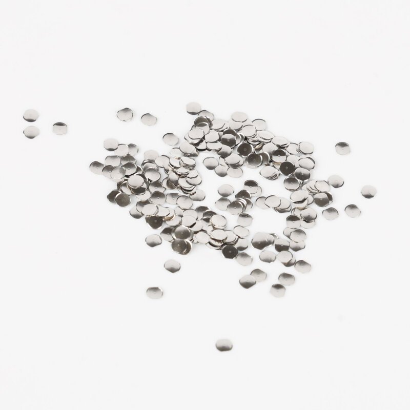
It is a sinking feeling for any electronics designer. You get the prototype boards back, you assemble the unit, and you go to press the power button. Nothing. Or maybe it works, but it feels “mushy,” like pressing into wet cardboard. Your first instinct is to blame the switch itself. Maybe the batch was bad? Maybe the force is wrong?
But nine times out of ten, when a round metal dome fails to perform, the dome is innocent. The culprit is almost always the green board underneath it. The PCB layout dictates the life, the feel, and the reliability of that switch. You can buy the most expensive, gold-plated dome in the world, but if the landing pad is designed poorly, it will fail. It’s a harsh reality, but getting the copper shapes right is just as important as the mechanical assembly.
The Geometry of the Landing Pad for a Round Metal Dome
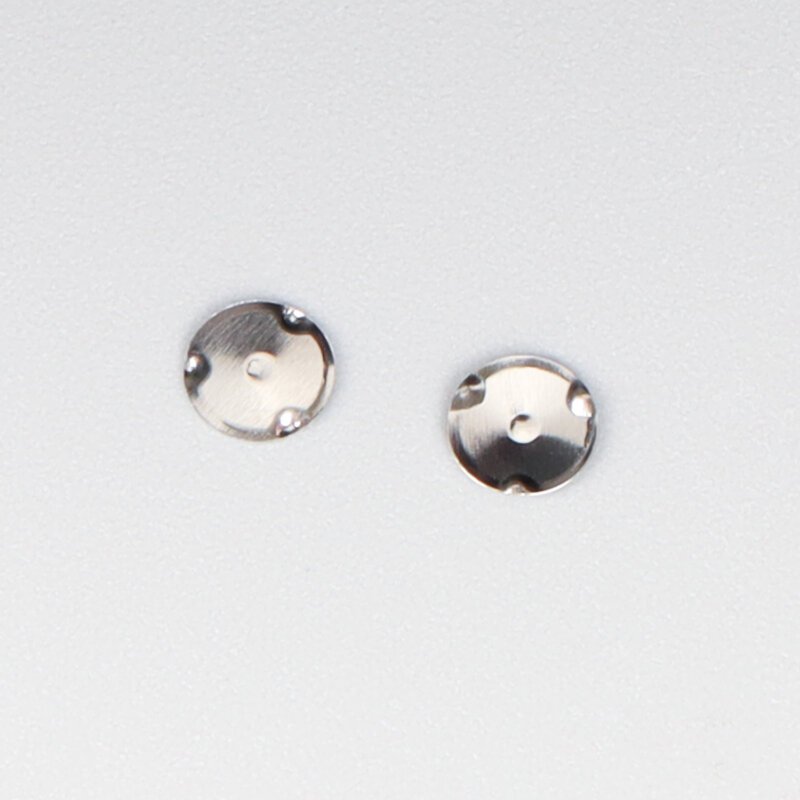
The basic concept seems simple enough. You have a center pad (one signal) and an outer ring (the other signal). The dome sits on the ring, and when you push the center, it touches the middle pad. Connection made. Simple, right?
Well, not exactly. The specific dimensions of these copper pads are critical. A common mistake is making the center pad too large. If the central copper area is too wide, the round metal dome will bridge the connection before it actually “snaps.” This is called “teasing” the switch. The electricity flows, but the user hasn’t felt the click yet. It creates a disconnect in the user’s brain—the device reacted, but they didn’t feel the confirmation.
Optimizing the Gap Width
The gap between the central pad and the outer ring needs to be balanced. It shouldn’t be so small that there is a risk of shorting during assembly, but not so wide that the dome misses the target.
- Rule of Thumb: The center pad should typically be about 40-50% of the dome’s diameter.
- The gap is usually kept around 0.5mm to 0.8mm depending on the dome size.
Venting Strategies for Round Metal Dome Reliability
This is the silent killer. Because a round metal dome has a continuous rim, it creates a very effective seal against the PCB. It’s basically a suction cup.
When you press the button, the volume of air inside the dome decreases. That air needs to go somewhere. If the PCB is solid underneath, the air compresses and pushes back against your finger. It increases the actuation force and kills the tactile “snap.” Even worse, when you let go, the vacuum effect can hold the dome down, causing the switch to stick in the “on” position.
Layout designers must include vent channels. These are shallow trenches in the solder mask or actual cuts in the copper connecting the inner cavity to the outside world.
- Vias: Placing a small hole (via) under the dome is the easiest way to vent air to the back of the board. However, it must be small enough that the dome dimple doesn’t get stuck in it.
- Surface Channels: If you can’t drill through, you need a channel in the spacer layer or a gap in the solder mask that leads the air out sideways.
Surface Finish Matters for the Round Metal Dome
The texture of the PCB surface is something you can feel through the switch. If you use a cheap finish like HASL (Hot Air Solder Leveling), the pads are bumpy. They are uneven. When the round metal dome sits on a lump of solder, it wobbles. It doesn’t sit flat.
This rocking motion causes two problems. First, it makes the click feel inconsistent. Second, it concentrates stress on specific points of the dome rim, which leads to premature cracking. The dome isn’t failing because it’s weak; it’s failing because it’s sitting on a jagged rock.
Recommended Finishes:
- ENIG (Electroless Nickel Immersion Gold): This is the gold standard, literally. It is perfectly flat and resists corrosion.
- Immersion Silver: Good flatness and conductivity, though it can tarnish over time if not sealed well.
- Hard Gold: Extremely durable for high-reliability applications, though more expensive.
Analyzing Common Failures and PCB Fixes
| Symptom | Probable PCB Layout Cause | The Fix |
|---|---|---|
| Switch feels “Dead” (No Snap) | Lack of venting (Air trapped). | Add a via hole or air channel. |
| Intermittent Contact (Flickering) | Center pad too small or mask too thick. | Increase pad size or reduce mask thickness. |
| Switch “Teasing” (Signal before Click) | Center pad is too large/high. | Shrink the center pad diameter. |
| Short Circuit (Always On) | Solder paste contamination. | Reduce stencil aperture size; keep solder away from contact area. |
| Dome Cracking Early | Uneven surface (HASL) or debris. | Switch to ENIG finish; ensure clean assembly. |
Solder Mask Considerations for Round Metal Dome Layout
The green stuff on the board (solder mask) has thickness. It’s usually about 25 microns thick, which sounds like nothing, but in the world of micro-switches, it’s a mountain.
If you cover the traces between the center pad and the outer ring with solder mask, you are essentially building a wall inside the switch. When the round metal dome tries to collapse, it might hit this wall of solder mask before it hits the center contact pad. This prevents electrical closure.
Managing Contamination and Debris
This isn’t strictly “layout,” but the layout influences it. If you place the switch pads right next to a component that requires a lot of solder paste (like a large shield or connector), you run the risk of flux and solder balls migrating under the dome during reflow.
Flux residue is sticky. If it gets under the dome, it acts like glue. The dome snaps down and sticks there. Or, the residue insulates the contact, and the switch stops working.
- Keep Out Zones: Design a “keep out” zone around the round metal dome where no solder paste is applied.
- Cleanliness: If you are soldering other parts nearby, the board needs to be washed thoroughly before the domes are applied.
If you want to know more about round metal dome, please read Round Metal Domes: Key Benefits and Common Uses.
Resource
- Galvanic Corrosion – Wikipedia: Understanding why mixing metals (like silver domes on tin pads) can cause long-term failure.
- Switch Debouncing: A technical look at what happens electrically when a switch closes, and why stable contact is vital.
Add Your Heading Text Here
Can I place a via directly in the center pad?
You can, and it is great for venting, but you have to be careful. The via should be “tented” (covered) on the back side to prevent solder from wicking up. On the top side, the hole must be small (usually < 0.3mm) so the dome’s dimple doesn’t get caught in it, which would damage the tactile feel.
Is it better to have a solid outer ring or a broken ring?
For a round metal dome, a solid continuous ring is usually best because it provides a uniform seat for the dome rim. However, some designers use a “C” shape or a broken ring to allow for trace routing. Just ensure the gap isn’t so big that the dome tilts into it.
Why is my switch bouncing (double signaling)?
All mechanical switches bounce. The metal vibrates when it hits. However, if the PCB pads are oxidized or dirty, the bounce lasts longer. While software “debouncing” fixes this, a clean gold layout minimizes the physical bounce time significantly.