
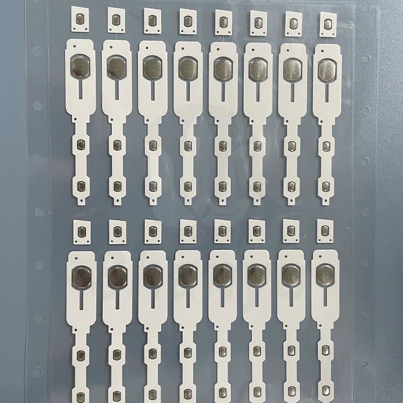
Getting Started with Metal Dome Array Placement on Circuit Boards
Placing a metal dome array onto a circuit board looks straightforward at first glance. Peel, stick, done—or so the thinking goes. But the difference between a functional assembly and one plagued by intermittent switches often comes down to technique and attention during this seemingly simple process.
The tactile switches found in remote controls, medical devices, and industrial panels all rely on proper dome placement. When done correctly, these assemblies last millions of cycles without issues. When rushed or executed carelessly, problems emerge almost immediately. Sometimes during testing, sometimes weeks later when products are already in customers’ hands.
This guide covers the practical aspects of placing metal dome arrays on circuit boards. Not theory, but actual methods that produce consistent results across different applications and production volumes.
Essential Preparation Before Placing Metal Dome Array
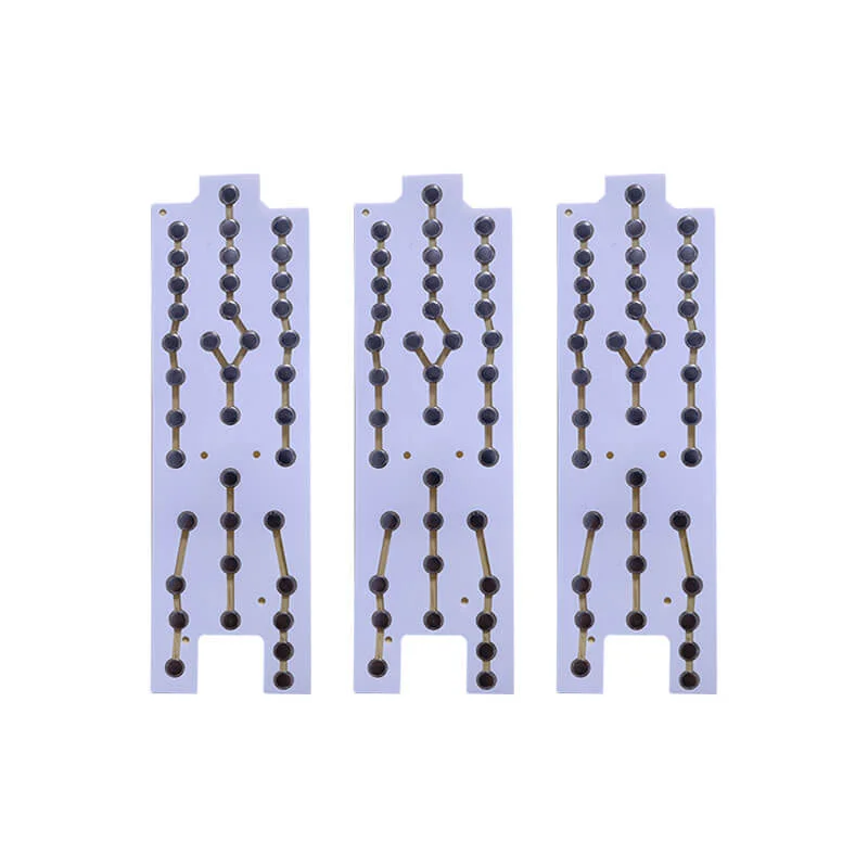
Circuit Board Surface Requirements
The landing zone for any metal dome array needs specific conditions. Contact pads must be clean—genuinely clean, not just visually acceptable. Invisible contamination causes invisible problems until switches start failing randomly.
Surface preparation involves several steps:
- Remove flux residue from soldering operations
- Clean with isopropyl alcohol using lint-free materials
- Allow complete evaporation before proceeding
- Inspect under bright lighting or magnification
- Re-clean any questionable areas
Oxidation on copper pads creates another common issue. Fresh boards rarely show this problem, but inventory that’s been sitting around develops surface oxidation that interferes with electrical contact. Light abrasion followed by cleaning addresses minor oxidation, though heavily affected boards may need replating.
Workspace Considerations
Environmental factors matter more than many realize when placing metal dome arrays. Temperature affects adhesive behavior significantly. Cold adhesive doesn’t flow properly into surface irregularities, resulting in weak bonds. Excessive heat causes premature tack that makes repositioning impossible.
The ideal workspace maintains:
- Temperature between 20-25°C
- Moderate humidity around 40-60%
- Clean air free from dust and particles
- Adequate lighting for visual inspection
- ESD protection measures in place
Tools and Materials for Metal Dome Array Placement
| Tool/Material | Purpose | Alternatives |
|---|---|---|
| Tweezers (non-magnetic) | Handling arrays without contamination | Clean gloves |
| Roller (small diameter) | Applying uniform pressure | Smooth squeegee |
| Alignment jig | Ensuring precise positioning | Registration pins |
| Magnifying lamp | Inspection during and after placement | Microscope station |
| IPA and wipes | Final surface cleaning | Other approved solvents |
| Anti-static mat | Protecting components from ESD | Grounded workstation |
Some operations benefit from vacuum placement equipment, especially for high-volume production. Manual placement works fine for prototypes and smaller runs, though consistency depends heavily on operator skill and attention.
Step-by-Step Process for Placing Metal Dome Array on Circuit Board
With preparation complete, the actual placement process follows a logical sequence. Rushing any step creates problems in subsequent ones.
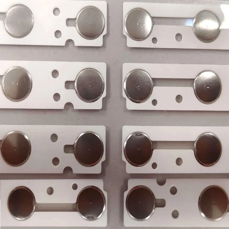
Array Inspection Before Placement
Before anything else, examine the metal dome array itself. Shipping and storage can cause damage that’s not immediately obvious. Look for:
- Domes sitting flat in their pockets (not tilted or displaced)
- Carrier film without tears or excessive wrinkles
- Adhesive backing intact and uncontaminated
- Correct part number matching circuit board requirements
A damaged array should never be installed hoping it will work. It won’t. Or worse, it might work during testing and fail later in the field.
Dry Fit Alignment Check
Position the metal dome array over the circuit board without removing any adhesive backing. This dry fit reveals alignment issues before they become permanent. Each dome should center directly over its corresponding contact pad.
Check registration from multiple angles. What looks aligned from directly above may show offset when viewed obliquely. Reference features help with positioning:
- Tooling holes matching PCB and array
- Board edges for alignment reference
- Printed alignment marks on PCB silkscreen
- Component positions as visual guides
Partial Backing Removal
Rather than exposing all adhesive at once, remove backing in stages. Peel back approximately one-third of the backing and fold it out of the way. This approach provides:
- Controlled exposure of adhesive
- Opportunity to tack down portion before committing fully
- Reduced risk of contaminating exposed adhesive
- Easier repositioning if initial contact isn’t perfect
Initial Tacking and Progressive Placement
With partial backing removed, carefully position the exposed section over its target area. Use registration features to guide alignment. When confident of positioning, allow the adhesive to contact the circuit board surface at one edge or corner.
From this tacked position:
- Verify alignment remains correct
- Apply light pressure to secure the initial contact area
- Gradually peel remaining backing while pressing down
- Work progressively across the array surface
- Keep slight tension to prevent bubbles or wrinkles
- Complete backing removal and final positioning
The progressive approach allows corrections early in the process when they’re still possible. Once fully adhered, repositioning risks damaging both the metal dome array and the circuit board surface.
Final Pressure Application
After complete placement, applying uniform pressure ensures proper adhesive bonding. A small roller works well for this purpose. Roll across the entire surface with moderate pressure, overlapping passes to cover all areas.
Pay special attention to:
- Edges and corners where lifting begins
- Areas immediately surrounding each dome
- Transition zones between dome clusters
- Any areas that appeared to have weak initial contact
Some adhesive specifications require specific pressure levels or dwell times. Following manufacturer recommendations ensures bond strength meets design requirements.
Wrapping Up Metal Dome Array Placement
Successful placement of metal dome arrays on circuit boards combines proper preparation with careful execution. Clean surfaces, appropriate environment, correct technique, and thorough verification all contribute to reliable assemblies. The time invested in doing each step correctly pays off through reduced rework and field failures. Taking shortcuts rarely saves time in the long run—problems just appear later when they’re more expensive to address. If you want to know more about metal dome array, please read about What Is a Metal Dome Array.
FAQ
What is the best temperature for placing a metal dome array on a circuit board?
Room temperature around 22-25°C works best for most adhesive types. Cold conditions below 15°C make adhesive stiff and less effective at bonding. High temperatures above 30°C can cause premature tack that prevents proper positioning. If workspace temperature falls outside the acceptable range, allowing materials to acclimate before placement helps considerably.
How soon after placing a metal dome array can the circuit board be used?
Handling strength develops within a few hours typically, but full adhesive cure requires 24 hours at room temperature for most products. During this curing period, avoid mechanical stress on the assembly. Critical applications sometimes specify extended curing times or elevated temperature curing cycles for maximum bond strength.
Can a metal dome array be repositioned after initial contact with the circuit board?
Very limited repositioning is possible immediately after contact if done carefully. Once pressed firmly or after adhesive begins setting, repositioning becomes impractical. The adhesive may separate from the carrier rather than from the board, damaging the array. If significant repositioning is needed, removing the array completely and starting fresh with new material produces better results than forcing adjustments.