
Building a keypad or control panel interface involves more than just slapping some buttons onto a board. The tactile feedback users expect comes from carefully arranged components working together. A dome switch array sits at the heart of many input devices, from TV remotes to industrial equipment panels. Creating one requires understanding the materials, the layout process, and honestly, a fair bit of patience. It seems simple until something goes slightly off and the whole thing feels wrong.

Understanding What a Dome Switch Array Actually Is
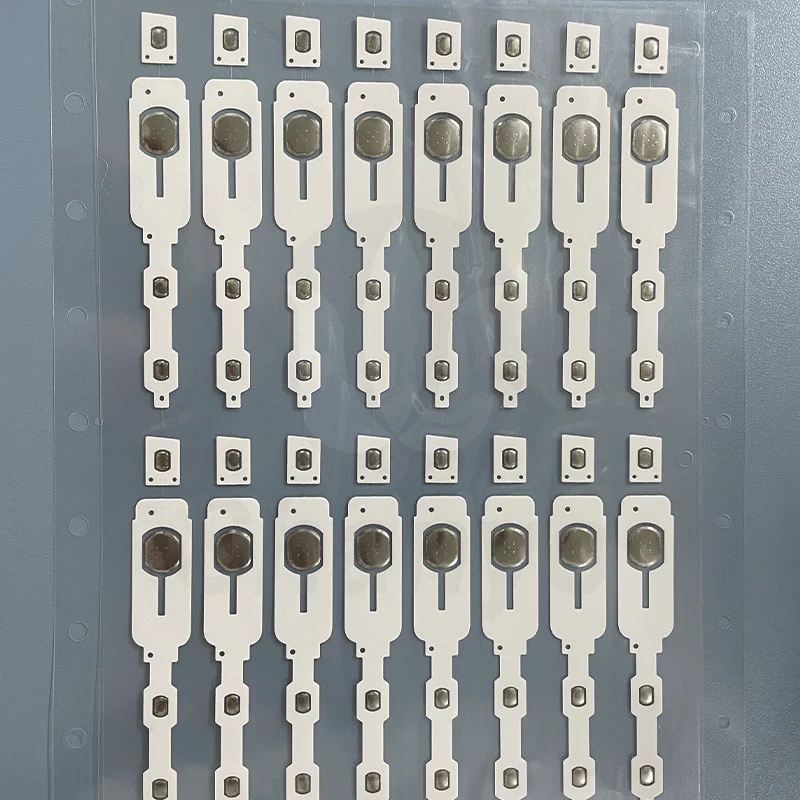
Before getting into fabrication, knowing what this component does helps frame the whole process. A dome switch array is essentially a collection of individual metal domes arranged in a specific pattern, usually held together by an adhesive carrier sheet. Each dome acts as a momentary switch. Press down, it clicks and makes contact. Release, it springs back.
The array format makes assembly efficient. Instead of placing dozens of individual domes one by one, a pre-arranged dome switch array gets positioned in a single step. Manufacturing loves this approach for obvious reasons. Faster production, fewer errors, consistent spacing between switches.
Where These Arrays Get Used
Applications are everywhere once you start noticing them:
- Remote controls and TV panels
- Medical device interfaces
- Automotive dashboard buttons
- Industrial control equipment
- Household appliance keypads
- Point-of-sale terminals
Pretty much anything with multiple buttons that need that satisfying click probably uses some form of this technology.
Materials Needed to Make a Dome Switch Array
Gathering the right materials beforehand prevents interruptions during assembly. Quality matters here more than some might expect. Cheap materials lead to inconsistent feel and shorter product life.
Core Components
The essentials include:
- Metal snap domes (stainless steel, sized appropriately)
- Polyester or polycarbonate carrier film
- Pressure-sensitive adhesive layer
- Spacer layer with dome cavities
- Release liner for protection
Tools and Equipment
Beyond materials, certain tools make the process manageable:
- Precision tweezers (non-magnetic preferred)
- Alignment jig or fixture
- Lamination roller or press
- Cutting tools for film trimming
- Clean workspace with ESD protection
Some operations use automated placement equipment, but smaller batches or prototypes often get assembled by hand. Either way, cleanliness cannot be overstated. A single dust particle under a dome changes how it feels.
Planning the Layout for Your Dome Switch Array
Layout planning happens before any physical assembly. Getting this wrong means starting over, which nobody enjoys.
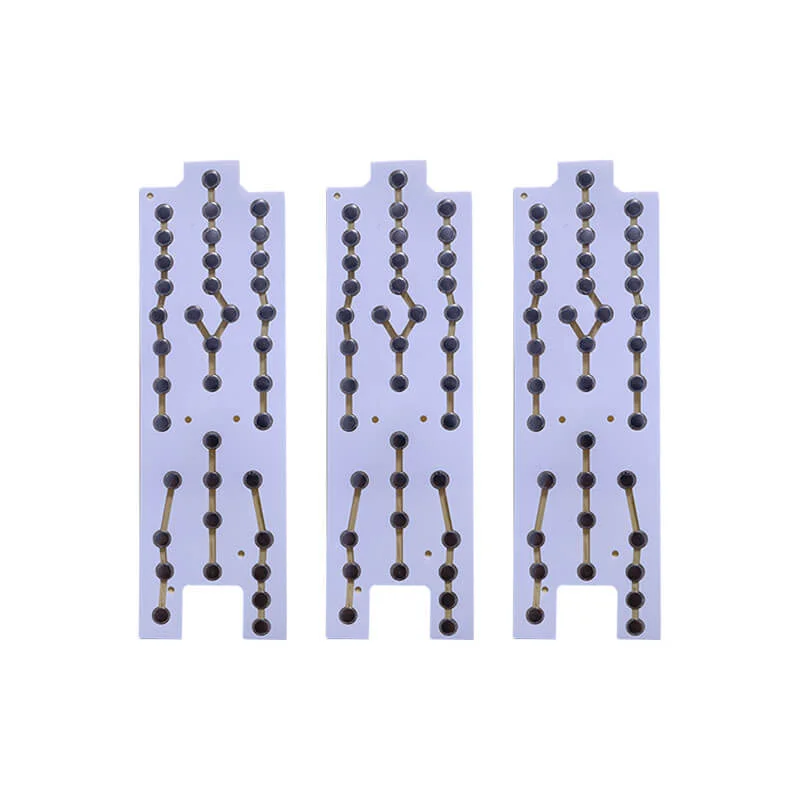
Determining Dome Positions
The PCB or circuit layer dictates where each dome needs to sit. Contact pads on the board must align perfectly with dome centers. Even a millimeter off and the electrical connection becomes unreliable.
Considerations during layout:
- Measure exact center points of each contact pad
- Account for dome diameter and ensure no overlap
- Leave adequate spacing for the carrier adhesive
- Consider the actuation angle if buttons are pressed at angles
- Verify dimensions match the overlay or keypad design
Selecting Dome Specifications
| Dome switch Type | Diameter Range | Force Range | Typical Feel |
|---|---|---|---|
| Round dome switch | 4mm – 16mm | 150g – 350g | Smooth, consistent |
| Four-leg dome switch | 5mm – 12mm | 180g – 400g | Crisp, defined snap |
| Triangle dome switch | 6mm – 10mm | 200g – 500g | Sharp, strong feedback |
| Oblong dome switch | 4mm x 6mm to 8mm x 12mm | 170g – 320g | Directional feel |
Choosing comes down to the application requirements. A medical device might need lighter actuation for gloved fingers. Industrial equipment often wants heavier force to prevent accidental presses.
Step-by-Step Process to Create a Dome Switch Array
With planning complete and materials ready, actual fabrication begins. The process has several stages, each requiring attention.
Preparing the Carrier Film
Start with the polyester carrier sheet. This film holds everything together and provides the adhesive surface that attaches to the PCB later.
- Cut the carrier to slightly larger than final dimensions
- Clean the surface thoroughly with isopropyl alcohol
- Allow complete drying before proceeding
- Apply the spacer layer with pre-cut dome cavities
- Ensure the spacer adhesive bonds fully without air pockets
The spacer layer is kind of critical. Those cavities create the space for domes to collapse when pressed. Wrong cavity size and the dome either cannot move properly or sits too loose.
Placing Individual Domes
This step demands precision. Each dome must sit centered in its cavity with the convex side facing up.
- Use tweezers to handle domes by edges only
- Place each dome into its corresponding cavity
- Verify orientation before moving to the next one
- Check that domes sit flat without tilting
- Inspect for any inverted or damaged pieces
A dome switch array with even one inverted dome feels noticeably different during use. The inconsistency stands out immediately when pressing across the keypad.
Final Trimming and Inspection
After lamination, trim the dome switch array to final dimensions. Edges should be clean without fraying or delamination.
Inspection checklist:
- All domes present and correctly oriented
- No visible contamination or particles
- Adhesive layers fully bonded
- Dimensions within tolerance
- Alignment marks visible if applicable
Testing a few switches by pressing helps confirm everything assembled correctly. The click should feel consistent across all positions.
FAQ
How many domes can fit in a single dome switch array?
There is no strict limit. Arrays can range from just a few domes for simple remotes to over a hundred for complex control panels. The limiting factors are the carrier sheet size, dome spacing requirements, and the corresponding PCB layout.
Can different dome types be mixed in one dome switch array?
Yes, mixing is possible and sometimes intentional. For example, a keypad might use lighter domes for frequently pressed buttons and heavier ones for critical functions that should not trigger accidentally. The spacer layer just needs cavities sized appropriately for each dome type.
What causes a dome switch array to feel mushy instead of clicky?
Mushiness usually results from incorrect cavity depth in the spacer layer, contamination under the domes, or using domes with actuation force too low for the overlay stiffness. Sometimes air trapped in the assembly also dampens the tactile response. Checking each of these factors helps identify the root cause.