
Getting metal dome switches to work properly on a PCB involves more than just dropping them onto contact pads. The layout matters. Pad geometry affects tactile feel. Spacing determines whether adjacent buttons interfere with each other. Done wrong, even high-quality domes will feel mushy or fail to register presses consistently.
This guide covers the practical aspects of PCB integration—the stuff that doesn’t always make it into component datasheets but absolutely affects real-world performance.
PCB Pad Design For Metal Dome Switches
Center Contact Pad Specifications
The center pad should be sized appropriately for the dome being used. Too large and the dome might make intermittent contact or feel inconsistent. Too small and contact resistance increases, potentially causing detection issues.
General sizing recommendations:
| Dome Diameter | Recommended Center Pad | Outer Ring Width |
|---|---|---|
| 4mm | 1.0-1.2mm | 0.4-0.5mm |
| 5mm | 1.2-1.5mm | 0.5-0.6mm |
| 6mm | 1.5-1.8mm | 0.5-0.7mm |
| 8mm | 2.0-2.5mm | 0.6-0.8mm |
| 10mm | 2.5-3.0mm | 0.7-1.0mm |
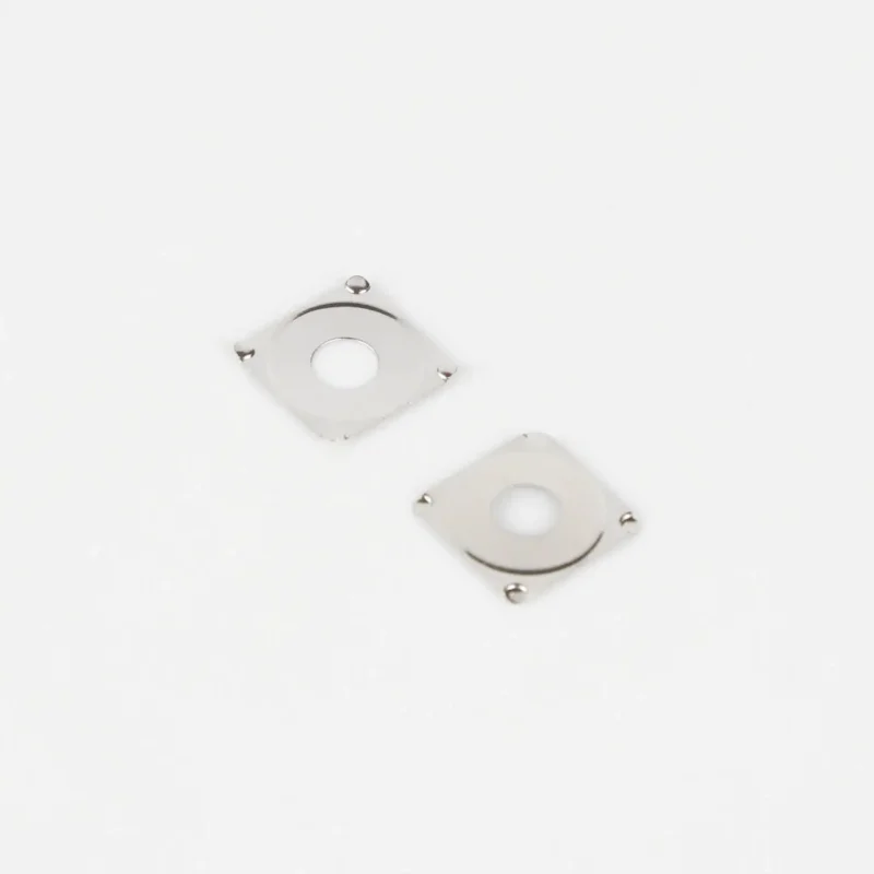
Outer Contact Ring Layout
The outer ring or pads need to support the dome legs evenly. Uneven support causes the dome to rock slightly, which affects tactile feel and can lead to angled actuation that wears unevenly over time.
For four-leg domes, the outer contacts typically form a broken ring with four segments aligned to the leg positions. Five-leg designs need five contact points, obviously. Some designers use a continuous ring instead of segmented pads—this works but uses more PCB real estate and may complicate routing.
The gap between center pad and outer ring is critical. Too narrow and there’s risk of solder bridges or contamination causing shorts. Too wide and the dome might not make reliable center contact when pressed.
Surface Finish Considerations
Pad surface finish affects both solderability and contact performance. Common options include:
- HASL (Hot Air Solder Leveling): economical but surface isn’t perfectly flat
- ENIG (Electroless Nickel Immersion Gold): flat surface, good conductivity, higher cost
- OSP (Organic Solderability Preservative): flat and affordable but less durable
- Hard gold plating: best for repeated contact but most expensive
For metal dome switches that will see millions of actuations, ENIG or hard gold generally perform better long-term. The flat surface also helps with consistent dome seating.
Placement And Spacing Of Metal Dome Switches
Getting spacing right matters more than some designers realize. Too close together and fingers activate adjacent switches accidentally. The overlay or membrane layer adds some tolerance here, but the underlying PCB layout sets the baseline.
Minimum recommended spacing between dome centers:
- Small domes (4-5mm): at least 8-10mm center to center
- Medium domes (6-8mm): at least 12-15mm center to center
- Large domes (10mm+): at least 18-20mm center to center
These numbers assume typical finger operation. Applications using styluses or gloved hands might need adjustments. Industrial equipment where operators wear heavy gloves often requires larger spacing than consumer electronics designed for bare-finger use.
Also worth considering—alignment with the overlay or membrane. The dome position on the PCB must match the actuator position on whatever sits above it. Even small misalignments (half a millimeter can matter) affect feel and consistency.
Assembly Methods For Metal Dome Switches
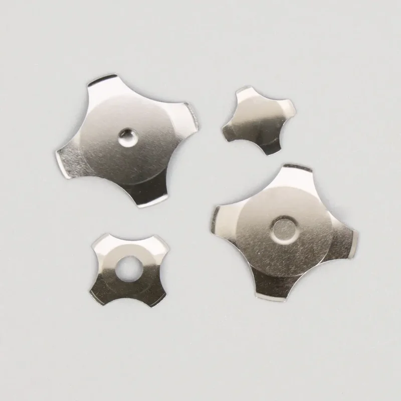
Dome Arrays Versus Individual Placement
Two basic approaches exist for getting domes onto boards:
Individual dome placement works for low volumes or prototypes. Each dome gets positioned manually or with pick-and-place equipment, then secured with adhesive or held by the membrane layer above.
Dome arrays (also called dome sheets) are more common in production. Multiple domes come pre-positioned on an adhesive carrier sheet, properly spaced for the specific PCB layout. Peel, align, stick—much faster than placing individual domes.
Custom dome arrays require tooling charges upfront but pay off quickly in assembly efficiency. For anything beyond prototype quantities, they’re usually the practical choice.
Retention Methods
Metal dome switches need something holding them in place. Options include:
- Adhesive backing on dome arrays
- Membrane switch overlay pressing down from above
- Dedicated retention frames (less common)
- Combination approaches
The retention method affects rework possibilities. Adhesive-mounted domes are difficult to reposition once placed. Membrane-retained designs allow easier dome replacement if needed during production troubleshooting.
Common Mistakes When Integrating Metal Dome Switches
Certain errors appear repeatedly in PCB designs involving dome switches:
- Inadequate clearance for dome height—the space between PCB and overlay must accommodate the dome’s profile
- Solder mask covering contact areas—pads need to be exposed, obviously, but sometimes mask apertures end up undersized
- Trace routing under domes—not always a problem, but can affect electrical characteristics in sensitive designs
- Ignoring thermal expansion—PCB and dome materials expand differently; large temperature swings can cause issues
- Forgetting about ESD protection—metal dome switches can be entry points for electrostatic discharge
FAQ
Can metal dome switches be used on flexible PCBs?
Yes, metal dome switches work well with flexible printed circuits. The flex material needs adequate support in the switch area to prevent excessive deflection during actuation. Stiffeners are sometimes added beneath dome locations on flex circuits.
What causes inconsistent tactile feel across multiple switches on the same board?
Inconsistent feel usually traces back to pad height variations (uneven solder mask or plating), dome seating issues, or misalignment between domes and overlay actuators. Verifying pad coplanarity and checking dome positioning typically identifies the root cause.
How much dome travel should the design accommodate?
Most metal dome switches have travel between 0.15mm and 0.3mm at actuation point. The total space between PCB and overlay should accommodate full dome compression plus some margin—typically 0.4mm to 0.6mm total depending on dome specifications.