
Designing a membrane switch or a simple keypad seems straightforward until the tactile feel just isn’t right. It is a common observation in the industry that the metal dome itself often gets the blame when the switch feels “mushy” or fails early, but frequently, the root cause is actually hiding underneath in the PCB layout. When integrating a custom metal dome into a design, the landing pad on the circuit board is just as critical as the dome specification itself.
The interaction between the dome and the board defines the user experience. It is not just about making electrical contact; it is about how the dome sits, how it moves, and how the air escapes. Here are five critical factors to consider, based on typical design challenges seen in production.
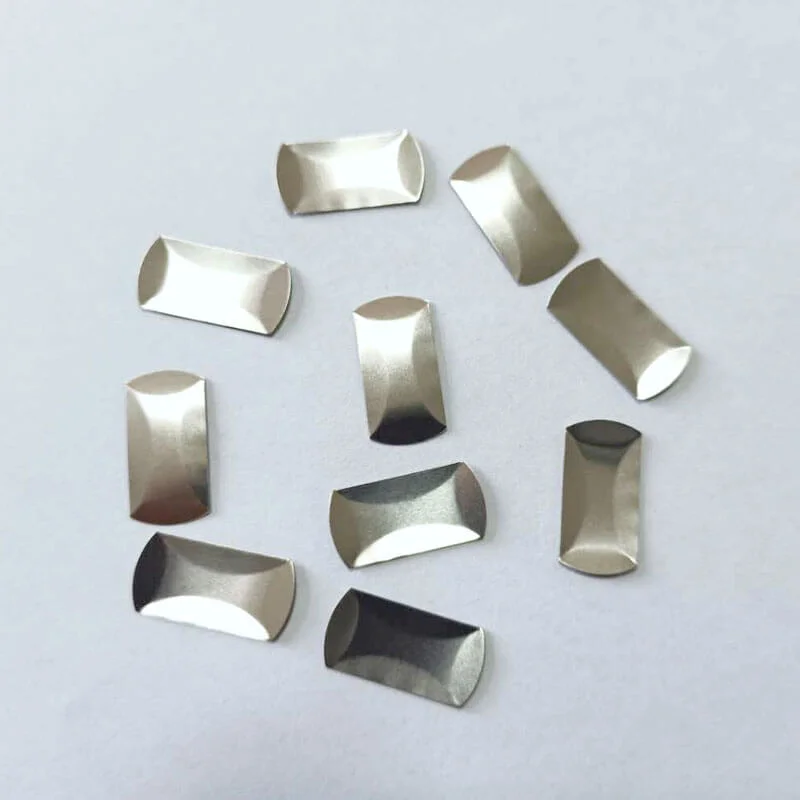
1. Optimizing Pad Geometry for the Custom Metal Dome
The shape and size of the contact pads are the foundation. A common mistake is making the central pad too small or the outer ring too narrow. If the outer ring doesn’t provide enough surface area, the custom metal dome might shift during actuation or, worse, during the assembly process.
Ideally, the central pad should be large enough to ensure contact even if the dome is slightly off-center (which happens in mass production), but not so large that it interferes with the “snap” action. The outer ring needs to support the feet of the dome fully. When the feet sit on the edge of a pad or, even worse, on the solder mask, the tactile ratio drops significantly. It is essentially about giving the dome a solid, flat floor to stand on.
2. Venting Strategies in Custom Metal Dome Integration
This is perhaps the most overlooked aspect. When a custom metal dome is pressed, the volume of air underneath it decreases. That air has to go somewhere. If the dome is sealed tight against the PCB without a venting channel, the trapped air acts like a spring, fighting against the user’s finger. This results in a switch that feels stiff or loses its crisp “click.”
You will often see designs where the air tries to escape through the spacer layer, but routing a vent trace directly on the PCB is usually more reliable. It connects the cavity under the dome to the outside world (or a different layout section).
- Venting Methods:
- PCB Trace Venting (connecting pads via a slit)
- Spacer Layer Channels
- Hole-through-board (less common for sealed units)
3. Choosing the Right Surface Finish for Custom Metal Dome Contacts
The choice of plating on the PCB pads dramatically affects both the longevity and the contact resistance of the switch. While it might be tempting to cut costs here, the interface between the custom metal dome and the board is a mechanical wear point. Every click scrapes the surface slightly.
From an observational perspective, Hard Gold (or Flash Gold over Nickel) is generally the gold standard—pun intended. It resists oxidation and handles the mechanical wear much better than HASL (Hot Air Solder Leveling) or OSP. HASL is particularly problematic because it is uneven; a dome sitting on a bumpy HASL pad will never feel consistent.
4. Managing Vias and Traces Near the Custom Metal Dome
A perfectly flat surface is non-negotiable. Placing vias (holes that connect PCB layers) directly under the custom metal dome footprint is a risky move unless they are tented or filled and capped. An open via under the dome can steal solder paste during assembly, or worse, the dome’s dimple could get stuck in the hole, leading to a switch that sticks down.
Similarly, running signal traces right under the outer rim of the dome creates uneven terrain. It creates a teeter-totter effect. The dome rocks back and forth instead of snapping cleanly. It is always better to route traces away from the immediate dome area or keep them on a lower layer.
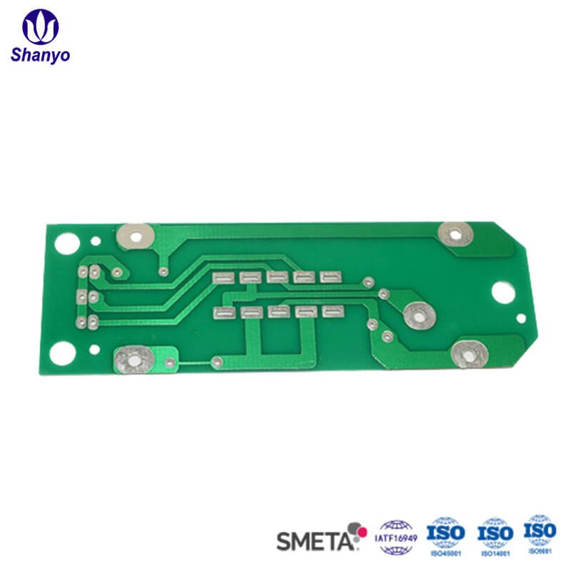
5. Solder Mask Clearance and Custom Metal Dome Placement
The solder mask (the green paint on most PCBs) has a thickness, usually around 1 mil (25 microns). It sounds negligible, but to a custom metal dome that only travels 0.3mm, it matters. If the mask encroaches too close to the pads, the dome might end up resting on the mask instead of the copper.
This “floating” effect changes the actuation force. The dome is pre-loaded before anyone even touches it. To avoid this, designers usually pull the solder mask back slightly from the landing area, leaving a clear gap between the pad and the mask. It ensures the dome sits metal-on-metal (or metal-on-substrate) without interference. If you want to know more about custom metal dome, please read The Complete Guide to Custom Metal Dome Design.
FAQ
Can I use a standard HASL finish for a Custom Metal Dome PCB?
It is generally discouraged. HASL leaves a domed, uneven surface on the pads. This causes the metal dome to wobble or sit unevenly, which ruins the tactile feel and can lead to intermittent electrical contact. ENIG or Hard Gold is much safer.
How wide should the vent channel be?
The vent doesn’t need to be huge. A trace width of 0.2mm to 0.3mm connecting the inner and outer pads (or venting outward) is usually sufficient to let the air escape without affecting the signal integrity or switch function.
Does the Custom Metal Dome always need a dimple?
Not always, but it helps. A dimple concentrates the force on the center pad of the PCB, which can help cut through light dust or oxidation. However, for ultra-thin designs, non-dimpled domes are sometimes used to save vertical space.