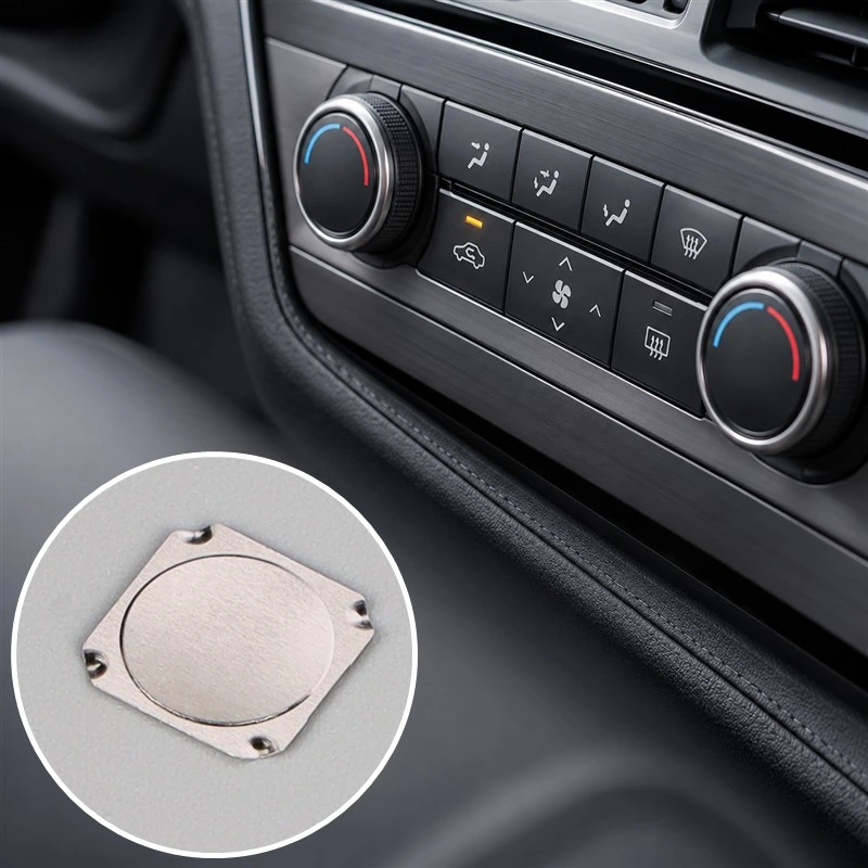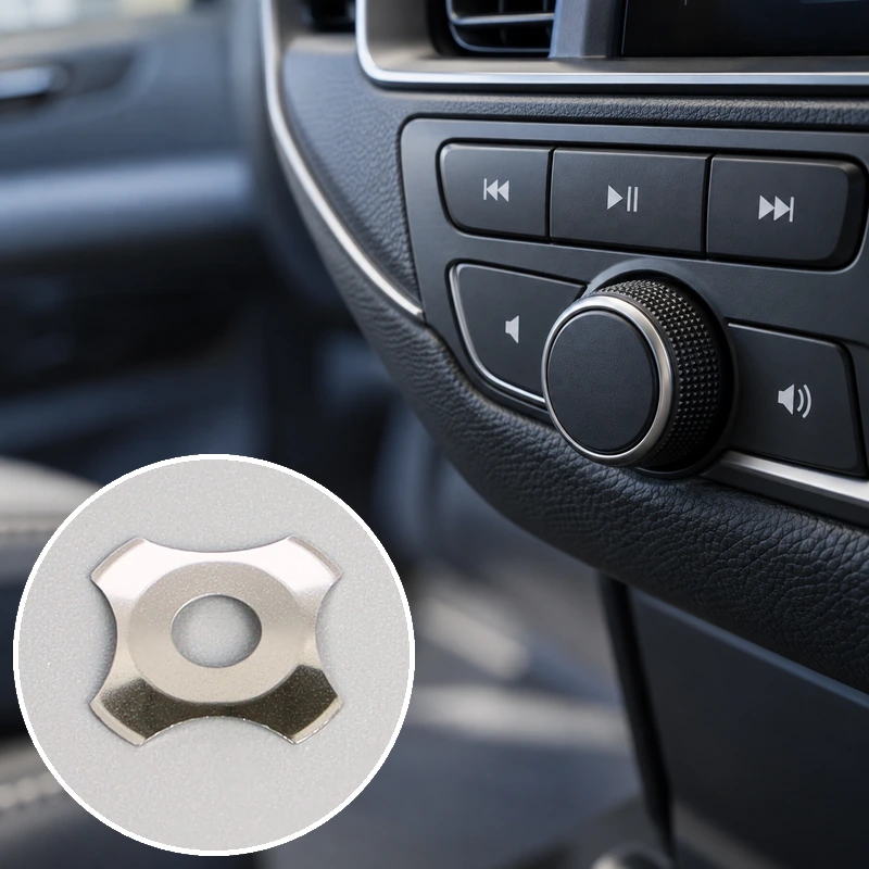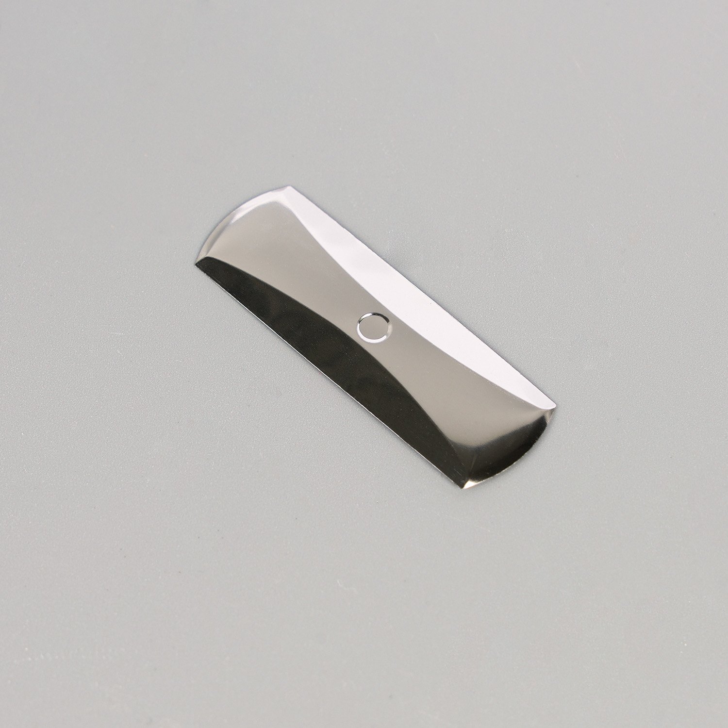
An interior button looks simple until it meets a validation plan. A custom tactile metal dome can sit inside its published tolerance on a bench and still behave differently once it is laminated under a carrier, pressed through a keycap, and mounted in a door module.
Validate at three levels before releasing a production design: the component against its drawing, the dome assembled into the real button stack, and the finished interface against the conditions of its mounting location. Each level answers a different question, and passing one does not prove the next.
What follows is what each level must produce and against which criteria.
What does validation cover before a dome enters production design?
Validation is the evidence that a design keeps its tactile and electrical behavior over the life of the vehicle, not only on the first sample. It runs at three levels and at two gates: design validation on engineering samples, then production validation on production tooling.
Component, assembly, and interface level
Component validation treats the dome as a stamped part: material hardness and thickness, formed height, burr height, curve shape, and plating thickness. It can pass cleanly while the assembly still disappoints, because nothing at this stage accounts for the load path.
Assembly validation follows the dome once it is laminated and installed, where the actuator, carrier, adhesive, and circuit change how it is loaded. Interface validation then puts the completed button into its environment: the temperature swing of its mounting location, humidity, vibration, and the press count the vehicle life implies.
Design validation and production validation are two gates, not one
Design validation uses engineering samples and asks whether the design can meet its requirements while drawings can still change. Production validation uses production tooling and asks whether that process reproduces the validated design consistently, which a perfect sample set never proves.
Why a supplier certificate is not design evidence
A component certificate or a catalogue cycle-life figure confirms one input and nothing more. Neither covers the load path, keycap alignment, cavity venting, or the sensing threshold of the circuit.
The two tracks run in parallel, and most programs walk both. A recent automotive RFQ for a solderable metal dome with gold plating and selective tin plating opened with a question about the plant rather than the part, moved through audit documentation and the customer’s CCL forms, and closed with a three-day on-site pre-audit covering cleanliness, tooling, stamping, testing and electroplating. That visit produced feedback rather than an approval, and it settled only half of the question: how the parts are made. Force, contact resistance and durability still had to come from the validation plan. The Valeo metal dome case study records that sequence.
| Level | Sample state | Question answered |
|---|---|---|
| コンポーネント | Stamped dome, pre-assembly | Does it match its drawing? |
| Assembly | Dome on carrier and circuit | Does the load path behave as designed? |
| Interface | Completed button in housing | Does it survive the vehicle environment? |
Which dome parameters have to be locked before you build samples?
Four numbers need to be fixed before sampling starts: actuation force, return force, travel, and tactile ratio. Plating and the pad finish it sits on come next, because together they decide whether contact resistance stays stable.
Actuation force, return force, and travel
Actuation force is the peak force needed to snap the dome through, return force is measured on the unloading branch as the dome recovers, rather than immediately after snap-through, and travel is how far the crown moves, usually a fraction of the formed height.
Specifying actuation force alone is the most common gap: a dome with light return force feels slow even when its trip force is on target, and a keycap travelling past the usable stroke leaves the dome partly collapsed.
Tactile ratio and the force-displacement curve
Tactile ratio compares peak force with the force the dome still resists after snapping, so a high ratio reads as a crisp click and a low one as a soft press. Because geometry, material, support, and test method affect the result, the agreed force-displacement curve is the specification, and the curve has to be recorded before and after the durability run.
Plating, pad finish, and contact resistance target
Plating and the mating pad are one decision rather than two. Define initial and post-life contact-resistance limits for the selected dome finish and mating pad, including measurement current, voltage, force, and conditioning. Neither a value below 100 mΩ nor a universal performance ranking of nickel and gold should be assumed without model-specific qualification data.
| パラメータ | What the drawing must state | How it is verified |
|---|---|---|
| 作動力 | Nominal value, tolerance, tip diameter | Force test on the agreed fixture |
| 反作用力 | Minimum value after actuation | Release branch of the curve |
| 旅行 | Value and reference plane | Measured against the support face |
| Tactile ratio | Minimum ratio | Calculated from the curve |
| 接触抵抗 | Initial and post-life limits | Four-wire measurement at rated force |
How do you validate the dome as part of the button stack?
Validate the stack by testing the dome through the production actuator, carrier, adhesive, and circuit rather than on a flat plate. A dome that passes bare often fails here, because the load is no longer centered and the support is no longer rigid.
Actuator geometry and centering
The actuator should meet the dome near its crown and stay centered through the stroke, with a tip diameter wide enough to load the crown predictably and narrow enough to clear the legs. Test the center, edges, and corners of the visible key, and record whether the dome still reaches full closure.
Carrier, adhesive, and vent path
On a multi-key panel the carrier fixes the coordinates, so registration accuracy becomes part of the electrical behavior, and adhesive squeezing into an active area changes both force and return. Air has to leave and re-enter the cavity on every press, which puts the vent route on the array drawing.
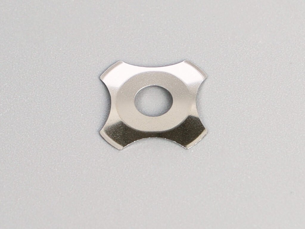
Pad layout, solder mask, and support flatness
The center contact and the surrounding ring have to be concentric with the dome, because off-center seating still clicks but at a different force. Support stiffness counts as much as the dome: on a flex circuit the backing plate is part of the electrical system.
Which electrical characteristics need a defined measurement method?
Contact resistance, insulation, contact bounce, and the operating current each need a method attached to the limit. A limit without a method is not repeatable between two laboratories, and that disagreement usually surfaces in production validation rather than in design.
Contact resistance and insulation
Contact resistance at signal level is a small number, so four-wire measurement is the only sensible method, since two-wire readings include probe and lead resistance that can exceed the value being measured. Pre-cycle the dome, then measure at rated force within a few seconds of actuation.
Contact bounce and the debounce window
A dome closes with a short burst of make-and-break before the contact settles, and published dome characteristics commonly put that bounce in the low millisecond range. Set the firmware debounce window from the bounce measured on the production assembly, and select hardware or software filtering and fault detection from the system safety requirements; hardware debounce is not a universal requirement.
Current and voltage limits
A dome is a signal-level contact that switches the input of a controller or a gate, not a load, whose switching current, voltage, power, and electrical life must be confirmed for the exact model and load; there is no universal 100 mA erosion threshold. Insulation and dielectric checks confirm that spacing and cleanliness survive exposure.
Which environmental tests apply, and who sets the conditions?
The customer sets the conditions, and they are derived from where the part is mounted rather than from what the part is. Cabin electronics usually cover roughly −40 °C to +85 °C, with wider ranges close to the engine or on exterior surfaces.
Test conditions follow the mounting location
The ISO 16750 series is the usual framework for these conditions. It’s five parts: separate general requirements, electrical loads, mechanical loads, climatic loads, and chemical loads, and its premise is that a component’s profile comes from its installation location rather than its category. ISO 16750-1 sets out that framework and the terminology the other parts use.
Temperature cycling, damp heat, and corrosion
Temperature cycling exposes differences in thermal expansion between the dome, the plating, the adhesive, and the substrate, and surfaces them as plating degradation and a gradual rise in resistance rather than a clean break. Damp heat and salt mist target the contact interface, and the tactile and electrical measurements have to be repeated after each exposure.
Vibration, mechanical shock, and ingress protection
Vibration testing looks at solder joints, connector retention, and structural resonance, and a dome resonating against its carrier can shift force distribution even when no single key fails. Ingress protection follows the finished assembly rather than the dome, and the vent is often the detail that breaks it.
Every exposure test ends with the same two questions: does the key still conduct, and does it still feel like the drawing?
How much life-test evidence is enough?
Enough means the durability run reflects the real assembly and the real electrical load and that the parameters measured after the run still meet the drawing. A cycle count with no drift data describes wear without describing whether the key still works.
Cycle targets differ by button location
A steering wheel key pressed on every trip and a seat memory key pressed twice a year do not need the same target, and one target for both either wastes cost or under-tests the high-use key. Targets belong to the button function and the vehicle life.
What to measure before and after the run
A useful durability report covers force drift, return force, travel, tactile ratio, contact resistance, bounce time, and appearance, measured on the same fixture before and after on a sample size large enough to show spread. Set the drift allowance from the feel requirement rather than from what a worn dome can still pass.
Why bare-dome life data does not qualify the finished key
Catalogue life figures come from a bare dome with no overlay, no carrier, and no over-travel, while production adds over-travel, actuator misalignment, substrate flex, contamination, and the real electrical load. For multi-key panels that ship as custom metal dome arrays, the tested sample has to match the production construction, including carrier thickness, adhesive, and vent pattern.
What documentation should go out with the part?
The release package should let a reviewer reconstruct the part and its process from the records without asking questions, which means dimensional, material, and process evidence plus revision control.
The submission package
A production submission typically includes a dimensional report on critical characteristics, material and plating certificates, process capability studies, measurement system analysis for the force and optical inspection equipment, a process failure mode analysis, and a control plan. Agree capability targets, characteristic classification, sampling, and submission level with the customer; Cpk 1.33 is not a universal acceptance criterion.
Those records only carry weight when the system behind them is audited in its own right. Shanyo holds IATF 16949 certification, with ISO 14001 and ISO 45001 alongside it, so the documents above are produced, approved and revised inside a quality system that automotive customers recognise, audit and keep under surveillance. The certificate does not replace PPAP and it is not design evidence, but it tells a reviewer that the process behind the part is defined, monitored and open to inspection.
Traceability and revision control
The dome drawing, array artwork, circuit data, adhesive die-cut file, and key stack drawing all describe one part, so their individual revisions must be linked in an approved configuration record, with the approved sample identified against that configuration. Related documents need not share a revision number.
Material compliance
Material composition declarations have to match what production actually uses, including plating chemistry and adhesive formulations. A declaration describing an earlier construction is worse than none.
When does a change force revalidation?
Any change that alters the load path, the contact interface, or the manufacturing process forces re-validation at the level it touches. The question is not how small the change looks, but whether the evidence on file still describes the part being shipped.
Changes that normally reopen validation include:
- Dome material, temper, thickness, or supplier.
- Plating type, thickness, or process.
- Forming tool, die maintenance that alters the curve, or a new press.
- Adhesive grade, carrier thickness, release liner, or die-cut pattern.
- Circuit pad layout, pad finish, or solder mask clearance.
- Actuator geometry, keycap travel, or hard stop position.
- Vent path changes that affect return speed.
- Firmware debounce settings, which are part of the electrical acceptance even though they sit outside the component.
Where a change touches only the assembly level, assembly evidence is enough. Where it touches the contact interface or the load path, the affected environmental and durability tests belong in the re-validation scope.
よくあるご質問
Does a metal dome need AEC-Q200 qualification?
Not in the sense that a capacitor or a resistor does. AEC-Q200 in its current revision covers listed families of passive electronic components, including capacitors, resistors, magnetic components, frequency devices, and fuses. An electromechanical snap dome is not one of those families, so the request usually means the customer’s own validation plan.
What is the difference between validating a bare dome and validating a finished keypad?
A bare dome can be measured against its drawing on a flat, rigid support with a defined press head. A finished keypad is a stack of overlay, actuator, adhesive, carrier, dome, circuit, and housing, and that stack changes the effective force, usable travel, and return behavior while adding contamination, flex, and electrical load.
How many press cycles should an automotive metal dome survive?
There is no useful universal number. A high-use control and an occasional key have very different duty cycles, so the target should follow the button function along with the vehicle life. What matters more is the evidence attached to it: which assembly was tested, at what force and electrical load, and how far force and resistance drifted.