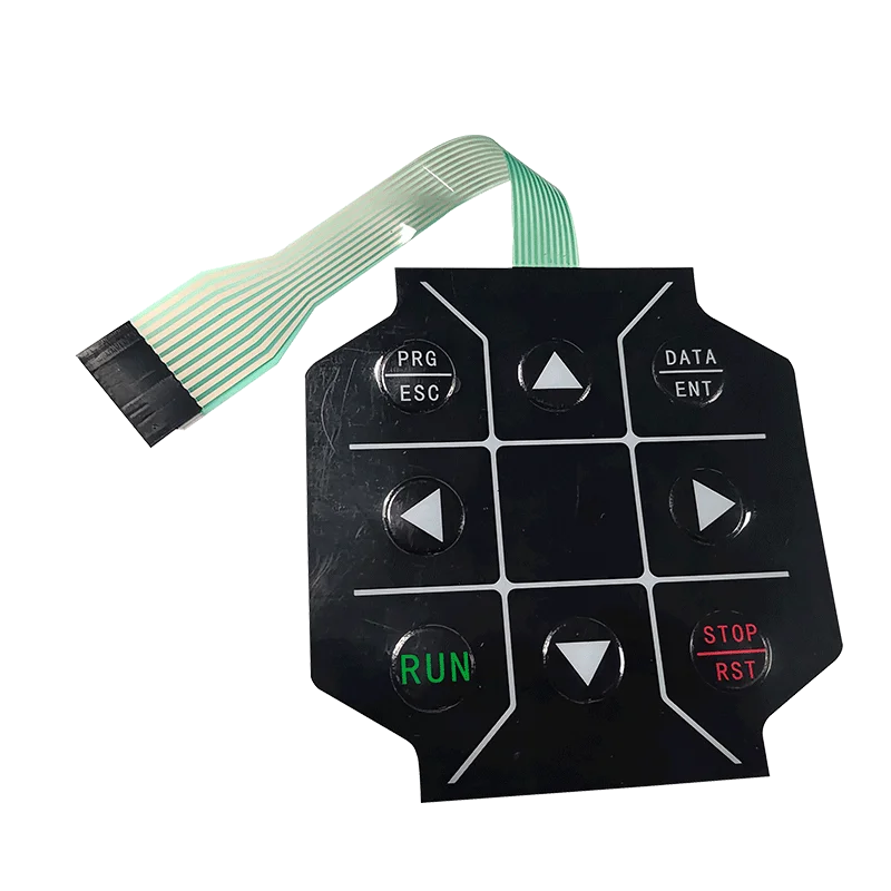
Behind every microwave keypad, medical device interface, and industrial control panel sits a membrane switch—manufactured through processes most people never consider. The finished product looks simple. Thin, flat, flexible. But creating these interfaces involves multiple specialized steps requiring precision and expertise.
Manufacturing a interruptor de membrana combines printing technology, materials science, and careful assembly. Each layer must meet exacting standards. Tolerances measured in thousandths of an inch matter here.
The journey from raw materials to finished interface reveals surprising complexity hidden within that deceptively simple appearance.
Raw Materials Used in Membrane Switch Production
Substrate Films
Polyester (PET) dominates membrane switch manufacturing. It offers the right combination of flexibility, durability, and dimensional stability. Typical thicknesses range from 0.075mm to 0.25mm depending on application requirements.
Polycarbonate sees use for graphic overlays needing better impact resistance or specific optical properties. It’s softer than polyester though—scratches more easily.
Conductive Inks
Silver-based conductive inks form the circuit traces. These specialized formulations contain tiny silver particles suspended in polymer binders. When printed and cured, they create electrically conductive pathways.
Carbon inks serve as alternatives for cost-sensitive applications or where silver migration concerns exist. Lower conductivity, but adequate for many designs.
Adhesive Materials
Pressure-sensitive adhesives bond everything together. Different formulations address various requirements:
- Standard acrylic adhesives for general applications
- High-temperature versions for demanding environments
- Medical-grade options for healthcare devices
- Removable types allowing rework
Spacer adhesives—with precisely cut holes—separate circuit layers at switch positions.
The Printing Stage in Membrane Switch Manufacturing
Screen Printing Fundamentals
Screen printing remains the workhorse of membrane switch production. Ink pushes through mesh screens with stenciled patterns, depositing controlled amounts onto substrates.
The process requires:
- Creating artwork files with proper layer separation
- Producing photo-emulsion screens for each color
- Setting up precise registration systems
- Printing each layer in correct sequence
- Curing between passes
Multiple passes build up graphic overlays—sometimes eight or more colors plus protective overcoats.
Circuit Printing Requirements
| Print Parameter | Graphics | Circuits |
|---|---|---|
| Typical tolerance | ±0.2mm | ±0.1mm |
| Layer thickness | Variable | Controlado |
| Defect sensitivity | Cosmetic concern | Functional failure |
| Cure requirements | Estándar | Critical |
| Inspection level | Visual | Electrical testing |
Digital Printing Options
Digital printing has gained ground for short runs and prototypes. No screens needed—graphics print directly from files. Faster setup, easier design changes.
However, digital approaches still can’t match screen printing for conductive inks or high-volume economics. Most production membrane switches still rely primarily on screen printing where it matters.
Die-Cutting and Forming Operations for Membrane Switch Components
Precision Die-Cutting
Steel-rule dies or matched metal dies cut individual components from printed sheets. Registration holes punched during printing ensure accurate alignment during cutting.
Critical cuts include:
- Graphic overlay outlines
- Display window openings
- Circuit layer profiles
- Spacer patterns with switch holes
- Connector tail shapes
Tolerances matter tremendously. Misaligned spacer holes cause switch failures. Offset overlay windows look obviously wrong.
Embossing Operations
When designs call for tactile buttons, embossing creates raised areas in the overlay. Matched male and female dies press the material into three-dimensional shapes.
Embossing happens after printing but before final assembly. The process requires careful temperature and pressure control—too aggressive and the material weakens or tears.
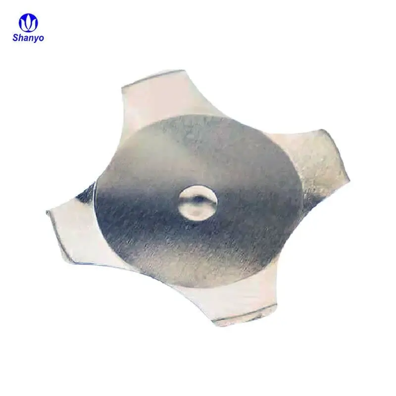
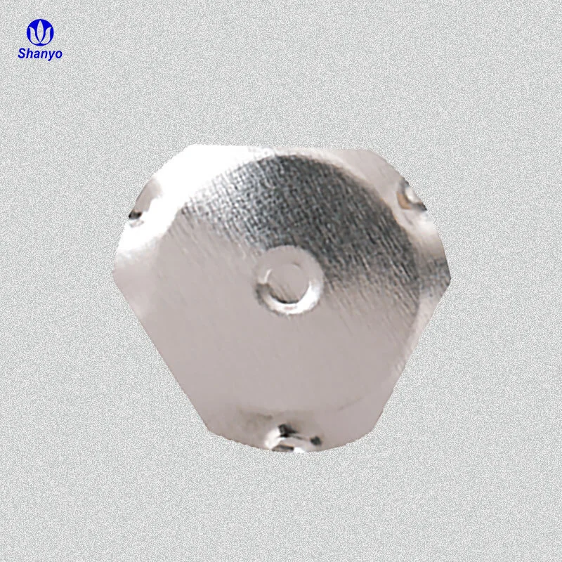
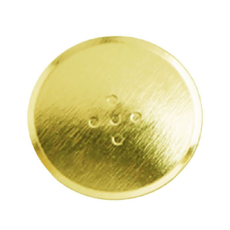
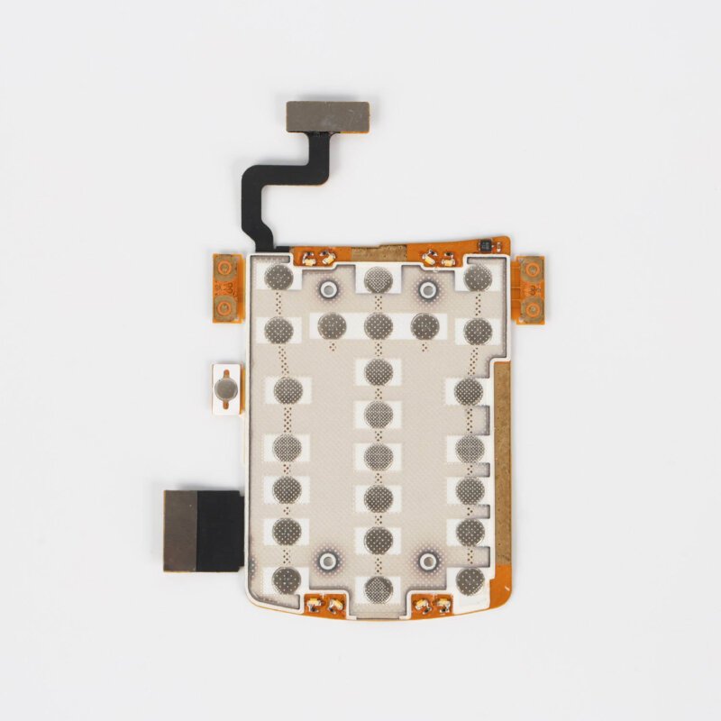
Metal Dome Preparation
Tactile membrane switches often incorporate metal domes. These tiny formed discs provide click feedback when pressed. Manufacturing involves:
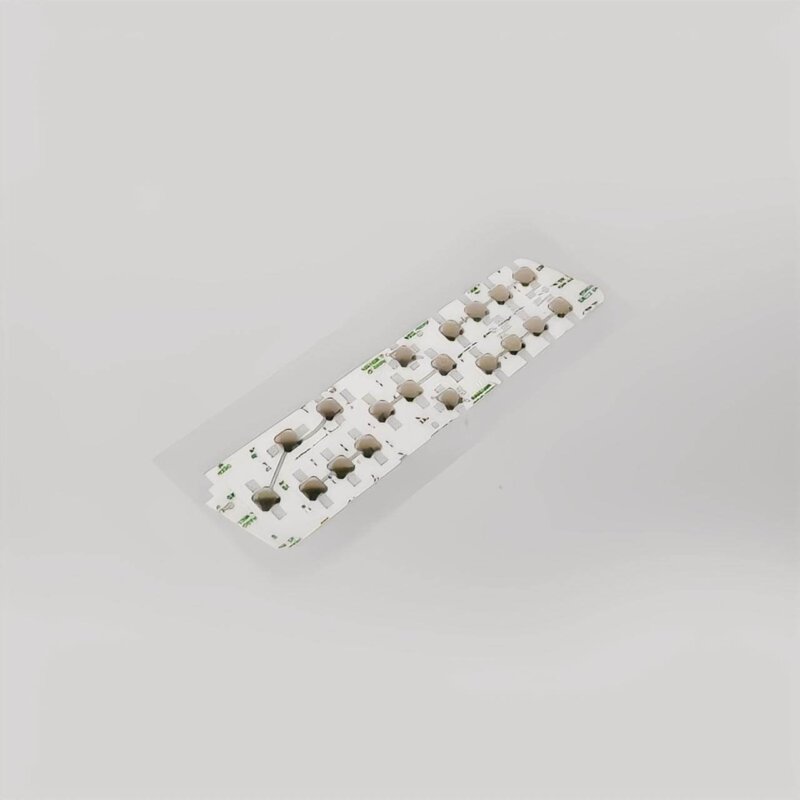
- Stamping domes from thin stainless steel
- Placing domes on carrier sheets or adhesive arrays
- Positioning precisely over circuit contact points
Dome placement requires accuracy within fractions of a millimeter. Mispositioned domes create inconsistent feel or non-functional switches.
Layer Assembly in Membrane Switch Construction
Registration Systems
Alignment holes or optical registration systems ensure layers stack correctly. Even small misalignments accumulate through multiple layers, potentially causing:
- Switch positions that don’t align with graphics
- Circuit contacts missing spacer holes
- Cosmetic defects visible through transparent overlays
Modern assembly equipment uses cameras and servo systems achieving registration within 0.05mm.
Lamination Process
Clean, controlled lamination prevents contamination between layers. Particles trapped during assembly cause switch failures—bumps preventing proper contact or debris shorting traces.
Lamination typically occurs in:
- Climate-controlled rooms
- Filtered air environments
- Controlled humidity conditions
Rollers or platens apply even pressure bonding adhesive layers. Some processes use heat activation. Others rely solely on pressure-sensitive adhesives. If you want to know more about membrane switch, please read Qué es un interruptor de membrana.
PREGUNTAS FRECUENTES
How long does it take to manufacture custom membrane switches?
Lead times vary considerably based on complexity and quantity. Simple designs with standard materials might ship within two to three weeks. Complex assemblies requiring custom tooling, specialized materials, or extensive testing could take six to eight weeks or longer. Prototyping often happens faster—some manufacturers offer rapid prototyping services delivering samples within days. Production quantities naturally require more time than prototype runs.
What quantities are economical for membrane switch manufacturing?
The economics depend on design complexity and tooling requirements. Screen printing setups involve significant preparation regardless of quantity, making very small runs expensive per unit. Most manufacturers suggest minimum orders of 100-500 pieces for reasonable economics. However, digital printing has lowered barriers for short runs and prototypes. High-volume production—thousands or tens of thousands—achieves the best per-unit costs as setup expenses spread across more units.
What causes defects during membrane switch manufacturing?
Contamination represents the most common defect source—particles between layers preventing proper switch function. Other common issues include printing defects (pinholes, bridging, incomplete coverage), misregistration between layers, adhesive failures, and handling damage. Environmental factors like humidity fluctuations affect adhesive performance. Improper curing of inks creates weak circuits. Experienced manufacturers maintain strict process controls minimizing these issues, but some defect rate is inevitable—making testing essential.