
Designing a мембранный переключатель involves balancing aesthetics, functionality, and manufacturability. It sounds straightforward on the surface—just some buttons and graphics, right? But the details matter enormously. Poor design choices lead to products that frustrate users, fail prematurely, or cost more than necessary to manufacture.
The best designs emerge from understanding how these interfaces actually work. Each decision affects others. Material choices influence circuit options. Button layouts impact user experience. Environmental requirements drive construction approaches.
Getting it right the first time saves considerable headache. Revisions after tooling creation become expensive fast.
Defining Requirements Before Membrane Switch Design Begins
Functional Requirements
What must the membrane switch actually do? Consider:
- Number of buttons or switch positions
- LED indicators needed
- Display window requirements
- Connector type and location preferences
- Integration with existing electronics
Document these thoroughly. Changing fundamental requirements mid-design wastes time and budget.
Environmental Considerations
Where will this interface operate? Environmental factors dramatically influence design decisions:
- Temperature range during operation and storage
- Humidity and moisture exposure
- Chemical contact possibilities
- UV exposure for outdoor applications
- Physical abuse expectations
A membrane switch for a kitchen appliance faces different challenges than one for outdoor industrial equipment. Design accordingly.
User Experience Goals
How should the interface feel to users? This includes:
- Tactile feedback preferences
- Actuation force requirements
- Button spacing and sizing
- Visual clarity and contrast needs
- Accessibility considerations
Sometimes clients overlook user experience initially—focusing only on electrical function. But the interface is what customers actually interact with. It deserves attention.
Graphic Overlay Design for Membrane Switch Interfaces
Material Selection
| Property | Polyester (PET) | Polycarbonate |
|---|---|---|
| Surface hardness | Higher | Lower |
| Scratch resistance | Better | Moderate |
| Chemical resistance | Good | Varies |
| Embossing capability | Limited | Excellent |
| Cost | Lower | Higher |
Texture and Finish Options
Surface texture affects both appearance and function. Options include:
- Glossy finishes for vibrant colors
- Matte textures reducing glare and fingerprints
- Velvet textures providing premium feel
- Selective texturing combining areas
Glossy surfaces scratch more visibly. Matte finishes sometimes appear less crisp. Trade-offs exist everywhere.
Graphic Layout Principles
Effective graphic design considers usability alongside aesthetics. Button areas need clear definition. Text must remain legible under expected lighting conditions. Color contrast affects visibility and accessibility.
Leave adequate margins around button graphics—embossing and tactile domes require space. Registration tolerances mean graphics shouldn’t crowd edges.
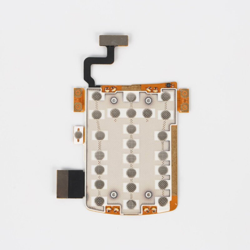
Tactile Feedback Options in Membrane Switch Design
Metal Dome Integration
Metal domes provide distinctive click feedback. They collapse with satisfying snap action when pressed, then spring back when released.
Dome selection involves choosing:
- Diameter (typically 8mm to 16mm)
- Actuation force (80g to 500g common)
- Material (stainless steel or nickel-plated)
- Snap ratio affecting click sharpness
Higher snap ratios create crisper, more noticeable clicks. Lower ratios feel softer.
Non-Tactile Approaches
Some applications intentionally avoid tactile feedback—flat membrane switch designs with visual or audible confirmation instead. Medical devices needing complete cleaning sometimes prefer smooth, featureless surfaces.
Non-tactile designs require clear alternative feedback mechanisms so users know their inputs registered.
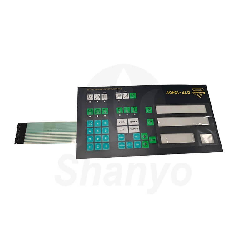
Connector and Tail Design for Membrane Switch Integration
Tail Configuration
The flexible tail extends from the switch body to reach the equipment’s circuit board. Design considerations include:
- Length reaching connector location with service loop
- Width accommodating required trace count
- Routing path avoiding interference
- Strain relief at body junction
Tail failures represent a common membrane switch failure mode. Adequate design prevents premature problems.
Termination Options
How the tail connects to equipment circuitry varies:
- ZIF connectors for easy insertion
- Crimp-style pin connectors
- Direct soldering to PCB
- Through-hole pin headers
ZIF connections dominate modern designs for their convenience and reliability. Other options suit specific application requirements. If you want to know more about membrane switch, please read Что такое мембранный переключатель.
ЧАСТО ЗАДАВАЕМЫЕ ВОПРОСЫ
How long does membrane switch design typically take?
Timeline varies considerably based on complexity and revision cycles. Simple designs with standard features might finalize within one to two weeks. Complex assemblies with custom requirements, multiple LED colors, specialized materials, or unusual features could require four to eight weeks of design development. Factor in prototype production and testing time—typically adding another two to four weeks before production approval.
What software tools work best for membrane switch design?
Adobe Illustrator handles graphic overlay design effectively, offering precise vector control and color management. Circuit layout benefits from PCB design software like Altium or KiCad, though some designers use specialized membrane switch tools. CAD programs like SolidWorks or AutoCAD produce mechanical drawings. Many manufacturers provide design templates and guidelines for their preferred file formats. Compatibility with manufacturer requirements matters more than which specific software generates the files.
Can existing membrane switch designs be modified easily?
Modification difficulty depends on what changes are needed. Graphic updates to text or colors typically cause minimal disruption. Adding or relocating switch positions usually requires circuit redesign and new tooling. Changing overall dimensions affects everything—tooling, artwork, circuit routing. Material changes might require design adjustments to accommodate different properties. Working from existing designs certainly saves time versus starting fresh, but significant modifications sometimes approach the effort of new designs.