Getting Started With Membrane Switch Panel Installation
Сайт панель мембранных переключателей arrives. Now what? Installation seems straightforward enough—peel backing, stick it down, plug it in. But rushing through this process often creates problems that show up later. Bubbles under the overlay. Edges lifting after a few weeks. Intermittent connections causing mysterious malfunctions.
Proper installation and interfacing requires attention to several details that aren’t immediately obvious. Taking time to do it right the first time prevents headaches down the road. Equipment manufacturers learn this lesson eventually, sometimes the hard way.
Preparing the Mounting Surface for Your Membrane Switch Panel
Surface preparation matters more than most people realize. The adhesive backing on a membrane switch panel needs specific conditions to bond properly.
Surface Requirements
The mounting surface should meet these criteria:
- Clean and free from oils, dust, or residue
- Smooth without significant texture or irregularities
- Structurally rigid to support the panel
- Appropriate material compatible with adhesive chemistry
Cleaning Procedures
Before mounting, clean thoroughly:
- Wipe surface with isopropyl alcohol (70% or higher concentration)
- Allow complete evaporation—rushing this step leaves residue
- Avoid touching cleaned area with bare fingers
- Inspect for remaining contamination under good lighting
- Repeat cleaning if any residue remains visible
Skipping or shortcutting the cleaning process is probably the most common installation mistake. Adhesive bonds to whatever’s on the surface, whether that’s the intended substrate or a film of manufacturing oils.
Physical Mounting of a Membrane Switch Panel
Alignment Considerations
| Alignment Method | Лучшее для | Technique |
| Visual alignment | Simple panels | Careful eye positioning before contact |
| Registration pins | Precision needs | Temporary pins through alignment holes |
| Edge guides | Rectangular cutouts | Align to machined edges |
| Hinge method | Large panels | Tape one edge, swing down carefully |
Applying Pressure
After positioning:
- Press from center outward to expel trapped air
- Apply firm, even pressure across entire surface
- Use a roller or squeegee for larger panels
- Обратите особое внимание на края и углы
- Allow adhesive to cure before applying operational stress
Temperature affects bonding. Most adhesives perform best between 18-25°C. Cold conditions slow curing. Excessive heat during installation can cause problems too.
Electrical Interfacing of a Membrane Switch Panel
Connector Types and Handling
Common connector configurations include:
- ZIF (Zero Insertion Force) connectors requiring locking mechanism engagement
- Crimp-style pin connectors
- Solder tail terminations
- Compression connectors
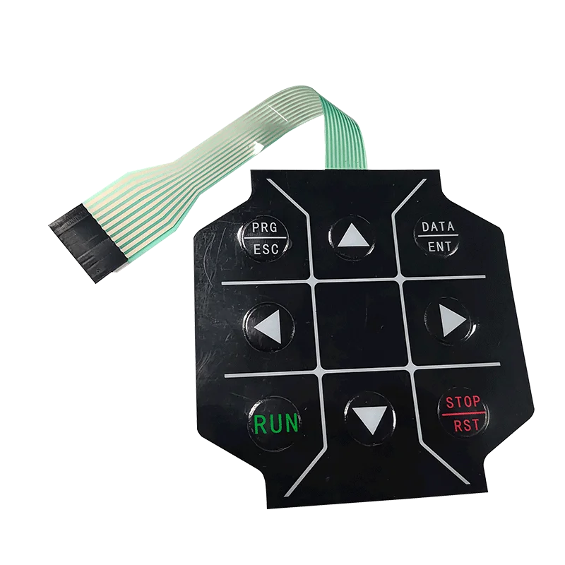
Handle the flexible circuit tail carefully. Creasing or sharp bends can damage conductive traces. Most manufacturers specify minimum bend radius—typically 3-5mm depending on construction.
Making the Connection
Steps for typical ZIF connector interfacing:
- Open connector locking mechanism fully
- Align circuit tail with connector, contacts facing correct direction
- Insert tail until it stops against connector body
- Close locking mechanism to secure connection
- Verify proper seating through visual inspection
- Gentle tug test confirms lock engagement
Reversed insertion or partial seating causes intermittent operation or complete failure. Worth double-checking before closing up equipment housings.
Circuit Verification
| Test | Назначение | Метод |
| Continuity | Verify trace integrity | Ohmmeter across circuit paths |
| Switch function | Confirm each button operates | Activate while monitoring |
| Resistance | Check connection quality | Measure through connector |
Post-Installation Testing for Membrane Switch Panel Assemblies
- Power up connected equipment
- Test each switch position individually
- Check tactile feedback consistency
- Verify indicator lights or displays if equipped
- Test rapid sequential presses
- Confirm no false triggers from adjacent areas
Document any issues found during testing. Patterns might indicate installation problems versus component defects.
Распространенные ошибки при установке, которых следует избегать
Frequently Seen Errors
Problems that keep appearing:
- Inadequate surface cleaning leaving contamination
- Rushing adhesive contact before proper alignment
- Excessive force during connector insertion
- Sharp bends in circuit tails
- Installing in temperature extremes
- Ignoring specified cure time before operational use
Экологические аспекты
Installation environment matters beyond just temperature. High humidity can affect adhesive performance. Dusty conditions risk contamination. Static discharge might damage sensitive electronics in some panel configurations.
Controlled conditions aren’t always possible, but awareness helps minimize risks.
Successful Membrane Switch Panel Integration
Installing and interfacing a membrane switch panel properly requires attention to surface preparation, careful mounting technique, and correct electrical connection. Rushing any step invites problems later. The process isn’t complicated, but it does demand patience and methodical execution.
Equipment that functions reliably for years often comes down to installation quality as much as component quality. Taking the time to do it right pays dividends throughout the product lifecycle. If you want to know more about membrane switch panel, please read What is a membrane switch panel.
ЧАСТО ЗАДАВАЕМЫЕ ВОПРОСЫ
Can a membrane switch panel be removed and reinstalled after initial mounting?
Removal is possible but rarely preserves the panel for reuse. Adhesive bonds are designed for permanent attachment. Attempting removal often damages either the panel or mounting surface. Replacement panels are typically required for reinstallation situations.
What causes intermittent operation after seemingly correct installation?
Intermittent issues usually trace to connector problems—partial insertion, contaminated contacts, or damaged tail conductors from improper handling. Less commonly, adhesive bonding failures allow panel movement that stresses internal connections.
How long should adhesive cure before equipment goes into service?
Full adhesive strength develops over 24-72 hours depending on formulation and conditions. Light operational use can typically begin within hours, but avoiding stress on bonds during initial curing improves long-term reliability.