The Basics of How a Membrane Switch Operates
They’re everywhere. Microwave ovens, remote controls, medical devices, industrial equipment. Мембранные переключатели quietly handle billions of button presses daily, yet most people never think about what happens beneath that flexible surface.
The operating principle is remarkably elegant. No complicated mechanisms. No moving parts in the traditional sense. Just thin layers working together to detect touch and transmit signals. Understanding how these interfaces function reveals why they’ve become so dominant in modern electronics.
Simple doesn’t mean unsophisticated though. There’s genuine engineering cleverness in how a membrane switch accomplishes its job.
Layer-by-Layer Construction of a Membrane Switch
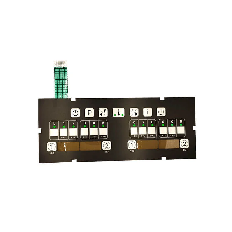
The Graphic Overlay
What users actually see and touch. This top layer typically consists of polyester or polycarbonate film, printed with graphics, labels, and indicators. It provides the visual interface—buttons, icons, text.
But the overlay does more than look pretty. It protects underlying layers from:
- Environmental contamination
- Moisture and spills
- UV degradation
- Physical wear and abrasion
Surface textures can be varied too. Glossy, matte, textured finishes all serve different functional and aesthetic purposes.
The Circuit Layers
Here’s where the actual switching happens. Two circuit layers—typically flexible polyester films—carry conductive traces printed in silver ink or carbon. These traces form electrical pathways connecting switch positions to the output connector.
The top circuit layer sits beneath the graphic overlay. The bottom circuit layer attaches to the backing. Between them? The crucial spacer layer.
The Spacer Layer
This adhesive layer holds the two circuits apart—usually by about 0.1 to 0.2 millimeters. Holes punched at each switch position allow the circuits to potentially meet. Without finger pressure, air gaps keep them separated. The spacer essentially creates thousands of tiny open switches, each waiting for activation.
The Activation Process Inside a Membrane Switch
Making Contact
Finger pressure deflects the flexible top circuit layer downward through the spacer hole. The conductive trace on top meets its counterpart on the bottom layer. Circuit completed. Signal generated.
The required pressure—typically 150 to 500 grams of force—can be engineered for specific applications. Medical devices might need light touch. Industrial controls might require firmer activation to prevent accidental triggering.
Breaking Contact
Release pressure and the polyester’s natural memory returns it to position. The circuit layers separate. Connection broken. Everything resets for the next press. This happens in milliseconds. The cycle can repeat millions of times over the switch’s lifetime.
| Компонент | Материал | Функция |
|---|---|---|
| Графическое наложение | Polyester/Polycarbonate | Пользовательский интерфейс и защита |
| Top Circuit | Polyester with silver ink | Upper conductive pathway |
| Проставка | Adhesive with holes | Сохраняет разделение до нажатия |
| Bottom Circuit | Polyester with silver ink | Lower conductive pathway |
| Rear Adhesive | Pressure-sensitive adhesive | Mounting to equipment |
Tactile Feedback Options in Membrane Switch Design
Non-Tactile Designs
The simplest configuration offers no physical feedback—just visual confirmation or audible beeps when pressed. These flat switches cost less and work fine for many applications. They’re common in appliances and basic controls.
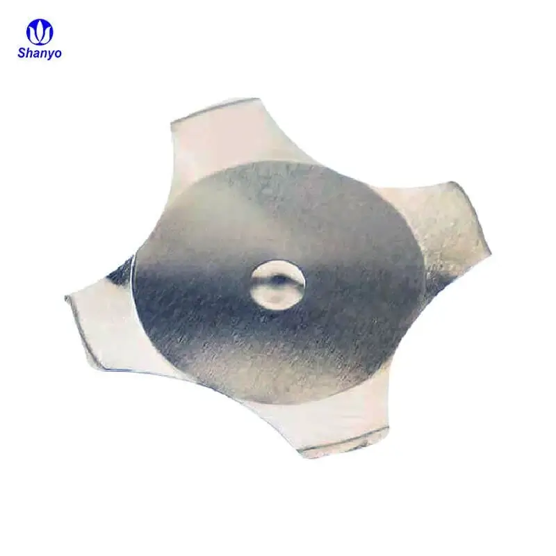
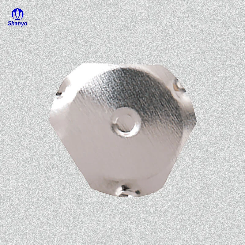
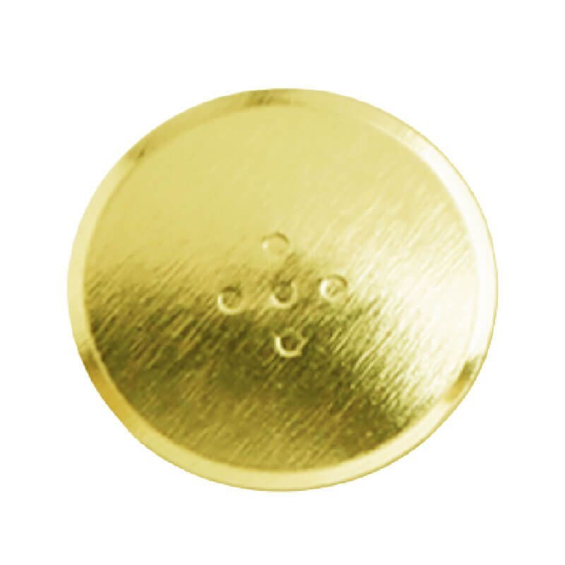
Metal Dome Enhancement
For applications needing physical feedback, metal domes change everything. These small, formed stainless steel or nickel-plated discs sit beneath each switch position. Pressing collapses the dome with a satisfying click. Users know the button registered.
Metal domes provide:
- Clear tactile response
- Audible click feedback
- Consistent activation force
- Improved durability
The snap ratio—how sharply the dome collapses—can be specified for different feel characteristics.
Polyester Dome Alternative
Similar concept, different material. Embossed polyester domes molded directly into circuit layers provide softer tactile feedback. Less crisp than metal, but adequate for many consumer applications. And cheaper to manufacture.
How Membrane Switch Circuits Transmit Information
Matrix Wiring
Most membrane switches use matrix configurations. Rather than dedicating individual wires to each switch, rows and columns create an addressing grid. A 4×4 matrix handles 16 switches with only 8 connections.
The controller scans rows and columns rapidly, detecting which intersections show continuity. This minimizes wiring complexity—important when space and connector size matter.
Analog Sensing
Some advanced membrane switch designs incorporate analog capabilities. Force-sensing resistors can detect pressure levels, not just on/off states. Position-sensing variants track finger location across continuous surfaces.
These specialized designs expand what membrane technology can accomplish beyond simple switching. If you want to know more about membrane switch, please read Что такое мембранный переключатель.
ЧАСТО ЗАДАВАЕМЫЕ ВОПРОСЫ
How long does a typical membrane switch last?
Lifespan depends heavily on design quality and usage conditions. Most manufacturers rate their switches for one million to five million actuations per position—sometimes more for premium designs. Calendar life typically ranges from five to fifteen years under normal conditions. Environmental factors like temperature extremes, moisture exposure, and chemical contact significantly affect longevity. Industrial-grade membrane switches built for demanding applications generally outlast consumer-grade versions.
What causes a membrane switch to fail?
Several failure modes exist. The most common involves wear-through of conductive traces after exceeding rated actuation cycles. Environmental damage from moisture infiltration or chemical exposure corrodes circuits. Adhesive failure causes layer separation, preventing proper contact. Connector damage from repeated flexing or improper handling breaks circuit continuity. Heavy-handed use accelerates mechanical wear. Age eventually degrades materials regardless of usage—polyester becomes brittle and adhesives lose grip over time.
Can membrane switches work in extreme temperatures?
Standard designs typically operate between -20°C and 60°C without problems. Specialized versions extend this range considerably—some handle -40°C to 80°C or beyond. Material selection matters critically for temperature extremes. Certain polyester formulations maintain flexibility in cold conditions. High-temperature adhesives prevent delamination in hot environments. Applications in automotive, aerospace, or outdoor industrial settings routinely specify temperature-resistant membrane switch designs tailored to specific operating conditions.