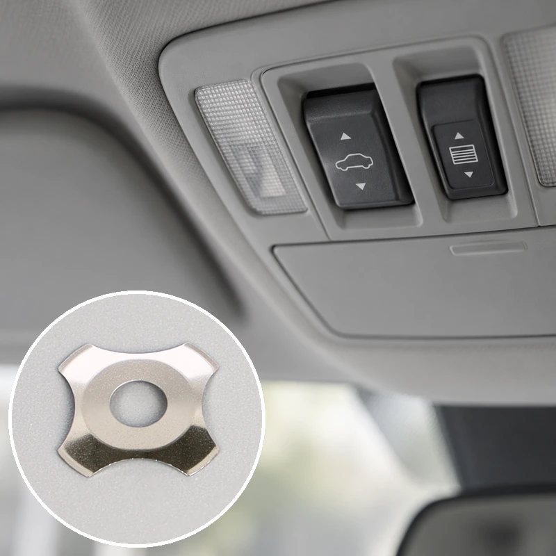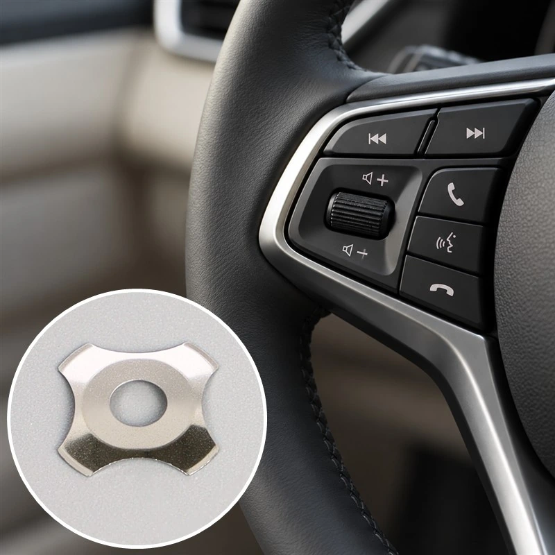
By the time a snap dome drawing is released, the steering wheel has already collected a heater mat, a backlit legend, a hands-on-detection layer and a molded keycap. Failures in this stack rarely come from the dome being wrong on paper. They come from nobody testing the parts of the stack the dome touches. Much of the evidence already sits with the custom metal dome manufacturer, and it tends to arrive after the drawing is frozen.
The short answer: validate the dome three times. First as a component, then inside the assembled tactile dome switch module, then as a part from the real production process. Within each gate, treat force and travel, contact resistance drift, environmental loads from the mounting location, and the supplier’s production evidence as separate acceptance items. A dome that passes on a bench fixture has cleared one gate of three.
The sections below follow that order, because a program hits them in that order.
What does validation mean before a steering wheel design is frozen?
Validation here means proving the dome works in the stack it will ship in, not that it matches its datasheet. That takes three sample states: loose or array-mounted domes, a production-representative module, and parts from the production tooling at the quoted rate.
Each gate fails differently, and skipping the middle one is the expensive shortcut: a wheel-level feel problem cannot be fixed with a different dome force.
| Gate | Sample state | What it proves | Who signs it off |
|---|---|---|---|
| Komponente | Loose domes or a dome array on the intended FPC or PCB | Curve, plating, dimensions, lot consistency | Supplier with the design engineer |
| Module | Keycap, actuator, carrier, backlight, heater and detection layers | Felt force, usable travel, contact, no interference | Module or Tier-1 owner |
| Production | Parts from production tooling at the quoted rate | The process holds the band in volume | Supplier quality and customer SQA |
What a dome datasheet can and cannot tell you
A datasheet force is measured on a flat fixture, with a defined probe and loading rate, on an unassembled part. That is a legitimate number and a useful starting point. It says nothing about how much force survives the keycap, whether the adhesive creeps through a winter of heater use, or whether the pad finish holds resistance after two hundred thousand presses. Ask for the measurement conditions in writing, then reproduce them before comparing suppliers.
Where the wheel changes the answer
Four things move the number a driver feels. A flexible backing absorbs travel, so the dome never reaches full snap. A heater mat or thick legend adds preload. A tall or off-centre actuator tip tilts the dome instead of loading the crown. A cavity with no vent slows the return, which reads as a soft key even with the right force.
Which force and travel values should you measure yourself?
Measure four things at every key position: trip force, return force, travel through the snap, and the ratio between peak and post-snap force. Use the actuator and support the design will use, and write the method into the acceptance file next to the numbers.
Force alone is a weak criterion. Two metal dome switches with the same trip force can feel completely different, because the contrast across the snap is what the driver reads as crisp or mushy.
| Parameter | How to measure it | Why it belongs in the file |
|---|---|---|
| Trip force | Force-displacement rig, intended probe and rate, dome on its production carrier | Sets the press the driver feels |
| Return force | The unloading half of the same curve | Too low means slow reset and missed presses |
| Travel to snap | Displacement from rest to the snap point | Stack clearance decides whether the snap is reachable |
| Click ratio | Peak force divided by post-snap force | Separates crisp from mushy at one nominal force |
Reading the force-travel curve
Plot the whole load and unload cycle rather than a peak. Mark the rest point, the peak, the moment of contact and the point where the dome breaks back. The shape between peak and contact tells you how the key feels at the keycap edge, where most thumbs land. A return branch far below the load branch points to a tilted actuator or a dome not seated flat.
The tolerance band matters more than the nominal value
Suppliers quote force tolerance in grams, and a tight figure looks reassuring. What a driver notices is the spread across the four or five keys within thumb reach. A panel where every key sits inside its band but the bands barely overlap still feels wrong. Set the band for the module, then work backwards to the component band that makes it achievable.
Shanyo publishes 1.5 N to 2.5 N for soft-touch interfaces and 2.5 N to 4.0 N where a definite click is wanted. Wheel keys usually sit at the firmer end, since the driver presses without looking, sometimes with gloves. Those ranges are a starting point for discussion, not an acceptance criterion for your wheel.
Preload, travel and the hard stop
Three measurements catch most preload problems early: the gap between actuator tip and dome crown at rest with the module assembled, the remaining travel after the stack closes, and the hard stop against the dome’s over-travel limit. A design with preload but no hard stop will eventually invert a dome. The metal dome button goes dead, and the dome gets blamed.
How do you validate the contact, not just the click?
Validate contact resistance as a drift, not a single reading. Measure at the start, after life cycling and after environmental exposure, then set the pass limit on the change between those points. Then measure bounce time on the real circuit and compare it with the debounce window of the input that reads it.
Resistance is normally measured with a four-wire connection at low voltage and current, so the test does not disturb the surface. A two-wire meter at normal test current can read through a film that would fail in service, which is why the method must be fixed before the first sample.
Resistance drift is the number to watch
Set two limits before life testing: an absolute ceiling and an allowed rise against the initial value. Fixing them afterwards invites an argument about whether a rise is real, and that argument always arrives at the worst moment. A rise points to fretting between dome leg and pad, plating worn through at the contact ring, or contamination inside the cavity. Log resistance with cycle count and test condition, not as one end figure.
Bounce time against the debounce window
A metal dome structure bounces. The contacts open and close a few times within the first fraction of a second, and the input circuit debounces that. The question is not whether bounce exists, but whether bounce plus settling fits the window the software allows. Test at the cold and hot extremes of the range. A key that reads clean at room temperature can double-register after a cold soak, and that failure looks like a software bug for weeks.
Venting and how fast the dome resets
Air has to leave the cavity on the press and return on release. If the vent is pinched by an adhesive bead or ends in a sealed pocket, the dome returns slowly, and slow return is what a driver calls a soft key. Check the vent on the assembled part, not the drawing.
Which environmental tests belong in a steering wheel plan?
Take test conditions from the mounting location, not from a generic automotive list. The ISO 16750 series sets out the electrical, mechanical, climatic and chemical loads a component sees at a given position in the vehicle, and a steering wheel is a cabin location with a heater bonded to it.
The series runs from general requirements through electrical, mechanical, climatic and chemical loads. It does not hand you a fixed test menu. It asks where the part sits, then derives conditions from that. Your customer’s specification still outranks it.
Heat and the heater layer
A wheel heater runs for long stretches in winter, with the dome carrier a few millimetres away. Adhesive softens, the carrier creeps, and the dome sits lower than it did on the bench. Felt force rises, usable travel falls, and the key feels abrupt. Run the force curve at the surface temperature the customer specifies, then after a thermal cycle.
Chemical and contamination loads
Cabin chemicals are constant rather than exotic: hand lotion, sanitizer, sunscreen, cleaning wipes. The chemical part of the ISO 16750 series covers fluid exposure, and the honest way to apply it is to test the actual stack with the substances the customer lists. Judge on resistance drift and appearance, not only on whether the key still clicks.
Vibration and micro-motion
Random vibration at module level is worth running, even though the wheel is a gentle environment. The risk is not a broken part. It is micro-motion between dome leg and pad, which polishes the finish, traps debris and raises resistance over time. Measure resistance after vibration at low signal level.
Where do steering wheel domes usually fail validation?
The same handful of failures appear across programs: a dome that inverts and does not return, adhesive that creeps under heat, an off-centre actuator that tilts the dome, a blocked vent, and a pad finish that wears through at the contact ring. Each leaves a signature in the data, which is why the method matters as much as the limit.
| Symptom | Likely cause | Check first | Re-test after the fix |
|---|---|---|---|
| Key dead after a hard press | Dome inverted past flat, no hard stop | Actuator travel against dome height | Curve and contact at that position |
| Force rises, travel shortens after a hot soak | Adhesive creep adding preload | Carrier adhesive and stack gap at temperature | Curve at the hot condition |
| Edge presses do not register | Actuator off-centre, keycap rocking | Tip diameter, guide clearance | Corner and edge press map |
| Slow reset, missed double press | Vent pinched by squeeze-out | Vent path on the assembled part | Bounce time at the cold extreme |
| Resistance climbs over life | Fretting, plating wear, contamination | Pad finish and wipe action | Drift after cycling |
None of these show up in a single pass or fail reading. They show up when the same parameter is measured at more than one point, which is why the sequence should be built before the samples arrive.
What evidence should the supplier hand over with the samples?
Ask for the system certificate, the PPAP package at the level your customer requires, and the raw data behind the samples. IATF 16949 certification tells you the supplier runs an automotive quality system. It does not tell you that this dome will hold its band in your stack.
The certificate describes the plant. The PPAP package describes the part, and a complete submission runs to eighteen elements across five levels, with level three the usual default. What matters here is the control plan, the measurement system study, initial process capability and the material and performance records.
Certification is the entry ticket, not the proof
Shanyo holds IATF 16949 certification, along with ISO 14001 and ISO 45001. That gets a supplier onto an approved list. It does not replace a dimensional report, a force curve for the actual lot, or a plating thickness certificate for the actual reel. Ask for data rather than a summary, because a one-page capability figure is easy to produce and hard to check.
What a pre-audit actually inspects
Supplier evaluation increasingly happens before the first production order, and it looks at process areas rather than paperwork. Shanyo’s record of the Valeo dome pre-audit is a useful reference: a request for a solderable dome with gold plating and selective tin plating, a three-day on-site review covering cleanliness, tooling, stamping, testing and electroplating, and feedback that noted prior work with material as thin as 0.02 mm. The audit asked how the part would be made.
What should be re-tested after a change?
Re-test whenever a change touches the load path or the contact interface. Material, plating, adhesive, carrier thickness, die-cut, tooling and packaging changes can all move force or resistance, and a component certificate alone will not show it.
| Change | Minimum re-test scope | Why it matters |
|---|---|---|
| Dome material or temper | Component curve, then module feel | Yield and snap move with temper |
| Plating type or thickness | Component curve, then life drift | Contact resistance and wear rate change |
| Adhesive or carrier construction | Module curve plus heat soak | Preload and vent path both shift |
| Die-cut or tooling replacement | Component dimensions, then module press map | Registration and seating move |
| Array layout or packaging | First-article check, module if registration moves | Placement error shows up at edge presses |
| Plant or line move | Full PPAP resubmission | Process evidence is tied to the site |
Anything that changes how the dome is formed, seated or contacted needs the module test repeated, because that is the only test that measures what the driver feels.
Frequently asked questions
Can a dome already approved for a keypad program be carried into a steering wheel?
Carry-over approval usually covers the part, not the application. The wheel adds a heater, a stiffer legend, a different actuator and a longer service expectation, so plan on module-level validation even when the component drawing does not change.
What changes when the wheel has a heater or a hands-on-detection layer?
The stack gets warmer and stiffer, which shifts preload and shortens usable travel, and the layers near the dome limit where adhesive and vent paths can run. Test the force curve at temperature, and confirm the vent is clear once the detection film and heater are laminated in place.
What should arrive with the sample domes?
A dimensional report, a force curve for the lot, a plating thickness certificate, a material certificate, the control plan excerpt and the measurement system study. Ask for raw files rather than a summary table, and ask which characteristics are checked every lot.